Projectile motion is the study of objects launched into the air and then moving under the influence of gravity alone, and it forms one of the most intuitive gateways into two-dimensional kinematics. A cricket ball struck toward the boundary, a fountain jet arcing across a courtyard, and a rescue package released from a hovering helicopter all obey the same underlying physics. This lesson isolates the conditions that make such motion predictable, then reveals the elegant idea that horizontal and vertical motions evolve independently of one another.
Building directly on the vector equations of motion developed in the previous lesson, this ninth installment of the course treats acceleration as a constant vector pointing vertically downward, with magnitude ##g \approx 9.8\ \text{m/s}^2##. That single assumption, combined with negligible air resistance, transforms a seemingly complex curved path into two simple straight-line problems solved simultaneously. Learners will see why the trajectory takes a parabolic shape and why the time of flight depends only on vertical quantities.
The treatment here stays deliberately conceptual, preparing the ground for the horizontal-launch analysis that follows in Lesson 10. By the end, readers should be able to state the defining assumptions of projectile motion, decompose an initial velocity into components, and explain, without hesitation, why a dropped ball and a horizontally fired ball strike the ground at the same instant.
On This Page
Defining Projectile Motion and Its Physical Conditions
Projectile motion describes the motion of any object that is given an initial velocity and thereafter moves freely through the air, influenced only by gravity. The launch may be horizontal, angled upward, or angled downward; what unites every case is that no propulsive force acts after release. The object is called a projectile, and its curved path is termed the trajectory.
The Idealised Assumptions Behind the Model
Physicists deliberately simplify reality to expose the essential structure of the phenomenon. Three assumptions define the standard model: the acceleration due to gravity is constant in magnitude and direction, air resistance is negligible, and the Earth's curvature and rotation can be ignored. These hold well for compact, dense objects travelling modest distances at moderate speeds.
Each assumption carries a measurable cost when violated. A table-tennis ball, light and large in cross-section, is slowed dramatically by drag and deviates from the ideal parabola. A long-range artillery shell, by contrast, flies far enough that the variation of ##g## with altitude and the planet's rotation become significant corrections rather than negligible footnotes.
Why Gravity Acts Only Vertically
Gravity is a central force directed toward the Earth's centre, which for local problems means straight down. Crucially, it possesses no horizontal component whatsoever. This asymmetry is the seed from which the entire analysis grows: the vertical direction experiences steady acceleration, while the horizontal direction experiences none at all.
Because acceleration is the rate of change of velocity, a zero horizontal acceleration means the horizontal velocity component remains frozen at its launch value for the entire flight. The vertical component, meanwhile, changes at the steady rate of ##9.8\ \text{m/s}## every second, decreasing on the way up and increasing on the way down.

Resolving Initial Velocity into Components
Every projectile problem begins with a single act of decomposition. The launch velocity ##\vec{v}_0##, specified by its magnitude and angle, must be split into perpendicular parts aligned with the chosen axes. Choosing horizontal as ##x## and vertical as ##y##, with upward positive, converts one slanted arrow into two independent numbers that drive the rest of the solution.
The Geometry of the Launch Angle
If the projectile leaves at speed ##v_0## at an angle ##\theta## above the horizontal, elementary trigonometry supplies both components instantly. The horizontal part is the adjacent side of the right triangle, and the vertical part is the opposite side. Mastery of this step removes most of the confusion beginners feel.
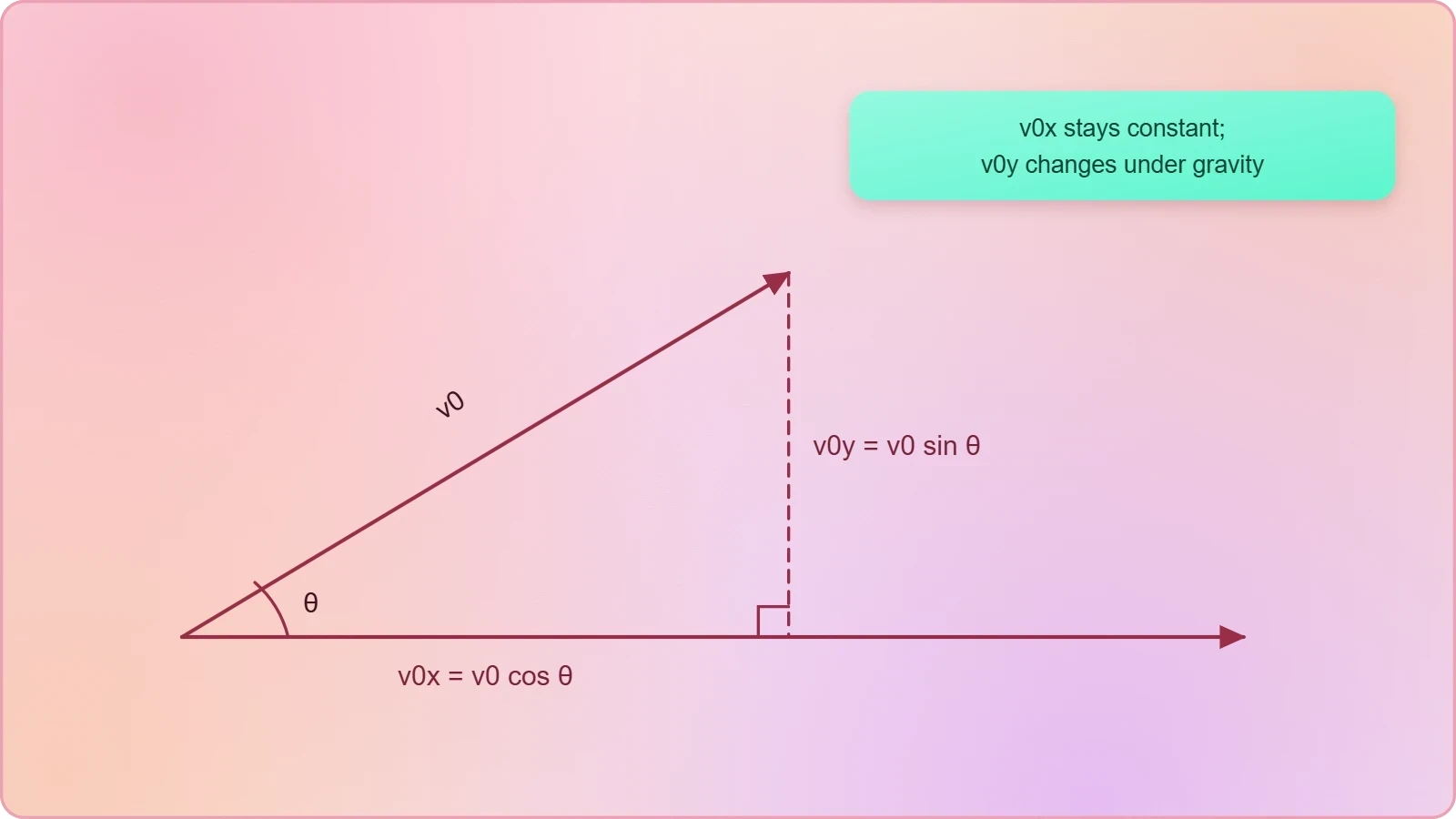
These two numbers carry very different destinies. The horizontal component ##v_{0x}## persists unchanged throughout the flight, while ##v_{0y}## is immediately subjected to gravitational deceleration. Recognising this divergence is the conceptual heart of the lesson and the foundation for every calculation that follows.
Sign Conventions and Axis Choices
Consistent sign conventions prevent the silent errors that plague projectile calculations. Adopting upward as positive makes ##a_y = -g##, so an object thrown upward has positive initial vertical velocity that shrinks, reaches zero at the apex, then turns negative as the object descends. The horizontal axis can point either way, provided the choice is fixed early.

Students who switch conventions midway through a problem inevitably produce contradictory answers. A disciplined approach writes the known quantities with explicit signs before touching any equation. This habit, though unglamorous, separates reliable problem-solvers from those who merely recognise formulas.
The Independence of Horizontal and Vertical Motion
The central revelation of projectile motion is that the two components evolve without any communication between them. Horizontal displacement accumulates at a perfectly steady rate, while vertical displacement follows the familiar pattern of uniformly accelerated motion. Neither component knows what the other is doing, yet together they trace a single graceful curve.
Galileo's Insight and the Two-Ball Demonstration
Galileo first articulated this independence by reasoning that a horizontally moving body retains its horizontal motion while simultaneously acquiring vertical motion from gravity. The classic demonstration makes the point vivid: one ball is dropped from rest while an identical ball is fired horizontally from the same height at the same instant. Both strike the ground together.
The horizontal launch gives the second ball a large sideways velocity, yet this contributes nothing to its fall. Its vertical motion is identical to that of the dropped ball, so the flight times match exactly. This result, counterintuitive to many first-time learners, is the cleanest experimental proof of component independence.

Solving the Two Motions Separately
Because the components are independent, each direction can be handled with the one-dimensional equations already mastered. The horizontal direction has zero acceleration, so displacement is simply velocity multiplied by time. The vertical direction uses the constant-acceleration equations with ##a_y = -g##, exactly as in free-fall problems.
The single quantity that links the two equations is time ##t##, which is common to both because the projectile exists in both directions simultaneously. This shared clock is the bridge between the horizontal and vertical worlds, and it is the key to solving every projectile problem encountered in this course.
The Parabolic Trajectory and Its Geometry
Eliminating time between the two component equations yields the shape of the path itself. Substituting ##t = x/(v_0\cos\theta)## into the vertical equation produces a relationship between ##y## and ##x## in which the horizontal coordinate appears squared. A quadratic relationship of this form is, by definition, a parabola opening downward.
Deriving the Equation of the Path
The derivation is short but instructive, and it rewards careful reading. Starting from the two component equations, we solve the horizontal one for time and substitute into the vertical one. The result expresses height purely as a function of horizontal distance, independent of any clock.
Every feature of the trajectory is encoded in this single expression. The linear term ##x\tan\theta## describes the straight line the projectile would follow without gravity, while the negative quadratic term represents gravity's persistent downward pull. The competition between these terms produces the familiar arch.

Symmetry, Apex, and Range
For launch and landing at the same height, the parabola is symmetric about its highest point. The apex occurs when the vertical velocity momentarily vanishes, and the time to reach it equals the time to return to launch height. This symmetry simplifies many calculations and offers a quick sanity check on answers.
The horizontal distance covered before returning to launch height is called the range, and it depends on both components through the launch speed and angle. Notably, complementary angles such as 30° and 60° yield identical ranges, a striking consequence of the trigonometric structure embedded in the path equation.
Applying the Model: A Worked Example
Abstract principles crystallise when applied to a concrete case. Consider a ball kicked from level ground at ##15\ \text{m/s}## at ##40^\circ## above the horizontal, with air resistance ignored. The task is to find the time of flight, the maximum height, and the horizontal range, using only the component equations already established.
Setting Up the Known Quantities
The first step is decomposition. The horizontal component is ##15\cos 40^\circ \approx 11.5\ \text{m/s}##, and the vertical component is ##15\sin 40^\circ \approx 9.6\ \text{m/s}##. With upward positive, the vertical acceleration is ##-9.8\ \text{m/s}^2## and the horizontal acceleration is zero.
Writing these values explicitly, with signs, before any calculation is the discipline that prevents errors. The vertical component is positive because the ball rises initially; the acceleration is negative because gravity opposes that rise. Every subsequent step flows mechanically from this setup.
Computing Flight Time, Height, and Range
Flight time follows from the vertical motion alone. The ball returns to ground level when its vertical displacement is zero, which yields ##t = 2v_{0y}/g \approx 1.96\ \text{s}##. The horizontal motion plays no role in determining how long the ball stays airborne.
Maximum height is reached at half the flight time, giving ##h = v_{0y}^2/(2g) \approx 4.7\ \text{m}##. The range then follows from the horizontal equation, ##R = v_{0x}t \approx 22.5\ \text{m}##. Each answer emerges from a single direction, confirming the independence principle in action.

import math

v0 = 15.0          # launch speed in m/s
theta = 40.0       # launch angle in degrees
g = 9.8            # gravitational acceleration

rad = math.radians(theta)
v0x = v0 * math.cos(rad)
v0y = v0 * math.sin(rad)

t_flight = 2 * v0y / g
h_max = v0y**2 / (2 * g)
r_range = v0x * t_flight

print(f"Horizontal component: {v0x:.2f} m/s")
print(f"Vertical component:   {v0y:.2f} m/s")
print(f"Time of flight:       {t_flight:.2f} s")
print(f"Maximum height:       {h_max:.2f} m")
print(f"Horizontal range:     {r_range:.2f} m")
Common Misconceptions and the Road Ahead
Several persistent misconceptions surround projectile motion, and naming them explicitly helps learners avoid them. The most common is the belief that a faster horizontal launch delays the fall. In truth, horizontal speed affects only how far the object travels, never when it lands. The vertical clock runs independently of sideways motion.
Where Beginners Typically Stumble
Another frequent error is assuming the velocity is zero at the apex. Only the vertical component vanishes there; the horizontal component persists unchanged, so the projectile continues moving forward at its launch horizontal speed. Confusing the components leads directly to this mistake.
Students also sometimes apply gravity to the horizontal direction or forget that the horizontal velocity is constant. A disciplined habit of writing the two directions as separate columns, with their own accelerations, eliminates both errors. The table above models exactly this separation.
Preparing for Horizontal Launch
The next lesson narrows the focus to the special case where the initial velocity is entirely horizontal, so ##\theta = 0## and the vertical component starts at zero. This simplification makes the mathematics especially clean and allows a sharper examination of how launch height alone governs flight time.
Everything needed for that analysis is already in place: the component decomposition, the independence principle, and the parabolic path equation. Learners who have internalised this lesson's framework will find the horizontal-launch case a natural and satisfying extension rather than a new topic altogether.
Also Read
- No links available.
From our network :
- Trump Political Strategy How Geopolitical Stunts Serve As Media Diversions
- Vite 6/7 'Cold Start' Regression in Massive Module GraphsIn-depth analysis of Vite 6/7 cold start regressions in massive module graphs. Learn about barrel file issues, pre-bundling optimizations, and how to improve Vite dev server performance.
- 98% of Global MBA Programs Now Prefer GRE Over GMAT Focus EditionExplore why 98% of global MBA programs now prefer the GRE over GMAT Focus. Learn about the shorter GRE format, verbal logic importance, and strategic versatility for students.
- 10 Physics Numerical Problems with Solutions for IIT JEEPrepare for IIT JEE with 10 physics numerical problems, complete with detailed solutions and conceptual explanations. Ideal for mastering kinematics, thermodynamics, electromagnetism, and optics.
- EV 2.0: The Solid-State Battery Breakthrough and Global Factory ExpansionDiscover the impact of the Solid-State Battery Breakthrough on the EV market. Learn about CATL and BYD stock growth, global factory expansion in Europe, and the future of EV 2.0 technology.
- Analyzing Trump Deportation Numbers Insights Into The 2026 Immigration Crackdown
- Mastering DB2 12.1 Instance Design: A Technical Deep Dive into Modern Database ArchitectureComprehensive guide to DB2 12.1 Instance Design. Explore architectural components, HADR setup, buffer pool tuning, and security policies for IBM DB2 12.1. Includes 10 functional SQL and Shell samples.
- Mastering DB2 LUW v12 Tables: A Comprehensive Technical GuideComprehensive guide on DB2 LUW v12 tables. Explore CREATE TABLE syntax, BLU Acceleration, range partitioning, data types, and security features for IBM DB2 LUW v12.
- AI-Powered 'Precision Diagnostic' Replaces Standard GRE Score ReportsDiscover the new GRE Precision Diagnostic. Learn how AI-powered behavioral analytics and time-to-solve tracking are replacing standard GRE score reports to empower students.
RESOURCES
- Projectile Motion | Physics - Lumen Learningcourses.lumenlearning.com... Introduction, where vertical and horizontal motions were seen to be independent. The key to analyzing two-dimensional projectile motion is to break it into ...
- Physics Study Guide: Projectile Motion, Forces & Laws | Notespearson.comIndependence: The horizontal and vertical motions are independent of each other. Classic Example: The Monkey and the Hunter. This classic physics problem ...
- 3.1 Kinematics in Two Dimensions: An Introductionpressbooks.bccampus.caUnderstand the independence of horizontal and vertical vectors in two-dimensional motion. A busy traffic intersection in New York showing vehicles moving on the ...
- 5.3 Projectile Motion - Physics - OpenStaxopenstax.orgMar 26, 2020 ... Since vertical and horizontal motions are independent, we can analyze them separately, along perpendicular axes. To do this, we separate ...
- Projectile Motion – Introductory Physics for the Health and Life ...openbooks.lib.msu.edu... independence of motion to solve projectile motion ... One of the most important things illustrated by projectile motion is that vertical and horizontal…
- 3.4 Projectile Motion - College Physics for AP® Courses - OpenStaxopenstax.orgAug 12, 2015 ... ... Introduction, where vertical and horizontal motions were seen to be independent. The key to analyzing two-dimensional projectile motion is ...
- Learn and try: Projectile motion (article) - Khan Academykhanacademy.org... moving in two dimensions with constant acceleration in each dimension. Discover the independence of a projectile's horizontal and vertical motions.
- Projectile Horizontal and Vertical Motion Independence Demonstratorresearchgate.netreplication and use in secondary school as instructional material. Keywords: Projectile motion, Instructional tool, User manual, Learning modules. Introduction.
- Starting to Think in Multiple Dimensions – Physics 131openbooks.library.umass.eduUnderstand the independence of horizontal and vertical vectors in two-dimensional motion. A busy traffic intersection in New York showing vehicles moving on the ...
- Understanding Projectile Motion | PDF - Scribdscribd.comIt defines a projectile as any object moved solely by gravity. Projectile motion has both horizontal and vertical components. The horizontal motion is constant, ...
- 3.4 Projectile Motion – College Physicspressbooks.uiowa.edu... Introduction, where vertical and horizontal motions were seen to be independent. The key to analyzing two-dimensional projectile motion is to break it into ...
- PPLATO | FLAP | PHYS 2.2: Projectile motionmet.reading.ac.uk... independence of the horizontal and vertical motions, and the lack of horizontal acceleration. 3.2 Vertical motion. In Subsection 2.4 we also stressed that ...
- Understanding projectile motion and its parabolic path - Facebookfacebook.comMay 31, 2026 ... Motion Horizontal (vertical component) Projectile) (constant) Vertical Motion ... Independence of Motion: Horizontal and vertical motions can be ...
- Projectile Motion - Horizontal and Vertical Components of Velocityphysicsclassroom.comA projectile moves along its path with a constant horizontal velocity. But its vertical velocity changes by -9.8 m/s each second of motion.
- Projectile Motion: Key Concepts and Calculations in Physics - Quizletquizlet.comAug 17, 2025 ... Galileo's work in 1632 established the independence of horizontal and vertical motions in projectile motion, which is foundational in physics.