Diffraction is the mechanism that explains why a conversation in an adjacent room remains audible even when no direct line of sight connects speaker and listener. When a sound wave encounters an obstacle or a finite aperture, its wavefronts do not terminate abruptly at the geometric shadow boundary; instead, they bend and spread into the region behind the barrier. This behaviour follows directly from Huygens' principle, which treats every point on a propagating wavefront as a secondary source of spherical wavelets. The envelope of these wavelets reconstructs the advancing wave, and near edges the reconstruction necessarily leaks energy into the shadow zone.
For IIT JEE aspirants, diffraction of sound deserves careful treatment because it exposes the wave nature of matter and energy in a measurable, everyday form. Unlike the reflection and refraction phenomena covered in the preceding lesson, diffraction is not a redirection at a surface but a redistribution of amplitude caused by spatial confinement of the wavefront. The controlling variable is the ratio of wavelength to obstacle or aperture size, and that ratio determines whether spreading is pronounced or negligible. Sound wavelengths in air range from roughly 17 millimetres at 20 kHz to 17 metres at 20 Hz, so audible sound diffracts around ordinary objects far more readily than light does.
This lesson develops the quantitative framework behind that observation. It establishes the conditions for observable diffraction, derives the single-slit minima condition, examines diffraction around solid obstacles, and connects the analysis to examination-style problems involving audibility behind barriers. The treatment builds on the superposition and interference machinery already established earlier in the course, and it prepares the ground for the acoustics of buildings, where diffraction and reflection jointly govern how sound distributes itself within enclosed spaces.
On This Page
- Foundations of Diffraction and the Wavelength-to-Aperture Ratio
- Quantitative Analysis and Frequency Dependence
- Problem-Solving Strategies and Examination Patterns
- Standard Problem Templates and Their Solution Sequences
- Common Errors and How to Avoid Them
- Error Patterns in Diffraction Problems
- Connecting Diffraction to the Wider Course
- Frequency Dependence of Diffraction Around a 0.30 m Aperture
- Diffraction Versus Interference: Conceptual Distinctions
- Lesson 11 Revision Checklist
Foundations of Diffraction and the Wavelength-to-Aperture Ratio
Diffraction becomes quantitatively significant only when the wavelength is comparable to, or larger than, the characteristic dimension of the obstacle or opening. When the aperture width ##a## greatly exceeds the wavelength ##\lambda##, the wavefront passes through almost undisturbed and the shadow is sharp. When ##a## approaches ##\lambda##, the emerging wavefront is strongly curved and energy spreads across a wide angular range. The dimensionless ratio ##\lambda/a## therefore serves as the natural diffraction parameter, and every qualitative prediction in this lesson can be traced back to its magnitude.
Huygens' Construction and the Origin of Spreading
Huygens' principle provides the geometric engine for diffraction. Each point on a wavefront acts as a source emitting a spherical wavelet, and the subsequent wavefront is the common tangent envelope of these wavelets. At an unobstructed plane wavefront the envelope remains planar, but at an aperture edge the missing wavelets on the blocked side leave the envelope free to curve inward. This curvature is the physical origin of the spread into the geometric shadow.
The construction also clarifies why diffraction is not a separate physical law but a consequence of superposition. The secondary wavelets interfere with one another, and the resulting amplitude at any field point is the phasor sum of contributions from every unobstructed point of the aperture. Fresnel's refinement, which assigns appropriate amplitude and phase factors to each wavelet, converts the qualitative picture into a calculable integral. For JEE purposes, the qualitative construction plus the single-slit minima formula covers the required depth.
A useful mental model treats the aperture as a finite array of coherent point sources. When the aperture is wide, the array is long and its radiation pattern is narrow, exactly as a long antenna array produces a narrow beam. When the aperture is narrow, the array is short and the pattern broadens. This analogy between diffraction and antenna directivity is exact in the far field and gives students a reliable intuition for predicting how the angular spread scales with aperture size.
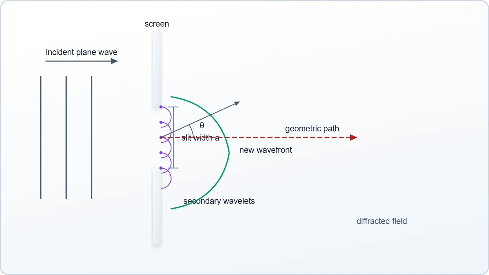
One common misconception deserves explicit correction. Diffraction does not require a physical edge; any spatial restriction of a wavefront produces it, including the finite size of a loudspeaker diaphragm or the mouth of a horn. The relevant dimension is always the smallest transverse extent of the emitting or transmitting aperture, measured in wavelengths. Recognising this generality prevents students from treating diffraction as a special case confined to slits and barriers.
The Single-Slit Minima Condition
For a plane sound wave incident normally on a slit of width ##a##, the far-field intensity pattern shows minima at angles satisfying a clean condition. Dividing the slit into two halves, each point in the upper half pairs with a point a distance ##a/2## below it, and destructive interference between each pair occurs when the path difference equals half a wavelength. This pairing argument yields the minima condition directly and avoids the full Fresnel integral.
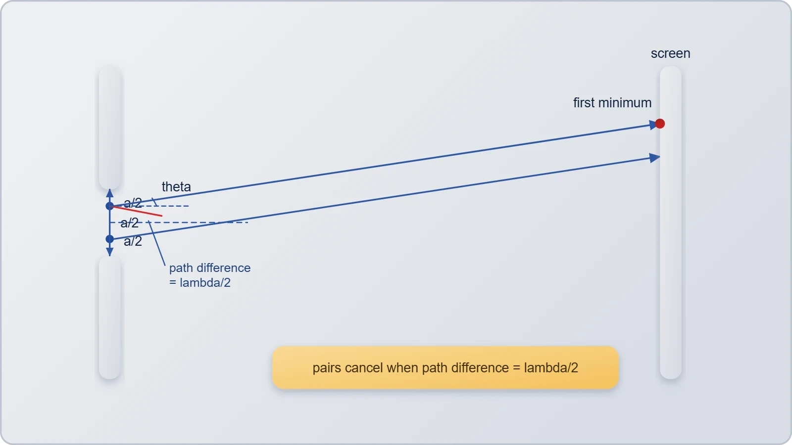
The central maximum lies between the ##m = +1## and ##m = -1## minima, so its angular half-width satisfies ##\sin\theta \approx \lambda/a## for small angles. The central lobe therefore subtends roughly ##2\lambda/a## radians, which confirms the inverse relationship between aperture width and spread. Secondary maxima of much lower intensity lie between successive minima, and their positions are not given by the simple half-integer formula that students sometimes assume.
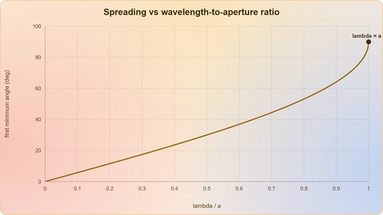
Two limiting cases anchor the formula. As ##a \to \infty## with fixed wavelength, ##\theta \to 0## and the pattern collapses to a geometric beam, recovering ray behaviour. As ##a \to \lambda##, the first minimum moves to ##\theta = 90^\circ## and the central maximum fills the entire forward half-space, meaning the slit radiates almost uniformly. Between these extremes the pattern evolves continuously, and examination questions frequently ask for the angle of the first minimum or the width of the central maximum.
For small angles the approximation ##\sin\theta \approx \theta## is standard, but JEE problems occasionally probe larger angles where it fails. At ##\theta = 30^\circ##, for instance, ##\sin\theta = 0.5## while ##\theta## in radians is 0.524, a discrepancy of about five per cent. Students should check whether the small-angle regime applies before substituting, particularly when the wavelength is a substantial fraction of the slit width.
Diffraction Around Obstacles and the Shadow Zone
Diffraction around a solid obstacle is the complement of diffraction through an aperture, and Babinet's principle links the two rigorously. The principle states that the diffraction pattern of an obstacle plus the pattern of a complementary aperture of identical outline sum to the unobstructed field. Consequently, the angular positions of minima and maxima around a thin obstacle coincide with those of a slit of the same width, although the intensity distributions differ in detail.
Behind a wide barrier the geometric shadow is not silent. Sound penetrates the shadow region with an amplitude that decays with distance into the shadow and with the ratio ##\lambda/a##. For a barrier of width much greater than the wavelength, the shadow is deep and the attenuation substantial; for a barrier comparable to or smaller than the wavelength, the sound wraps around it almost completely. This is why low-frequency noise passes around buildings and walls far more effectively than high-frequency noise.
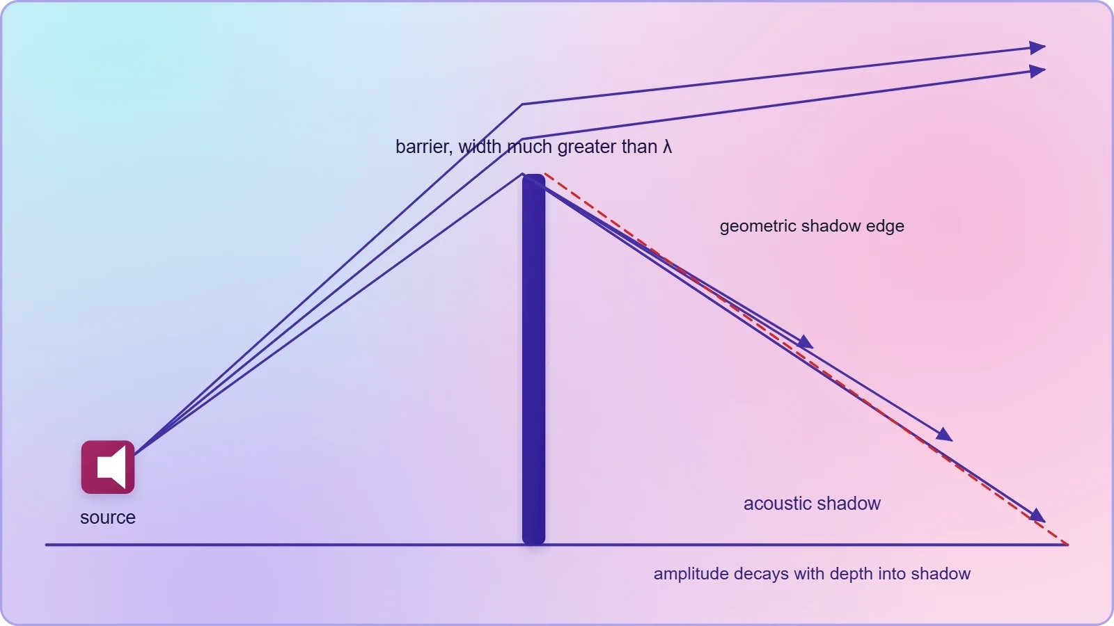
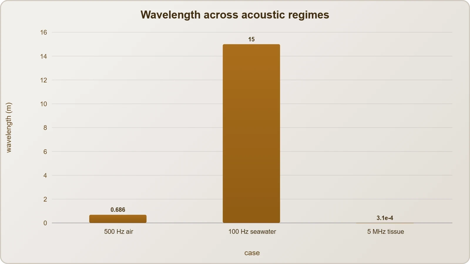
The practical consequence appears in noise-control engineering. A highway sound barrier designed to attenuate 500 Hz traffic noise, where ##\lambda \approx 0.69## m, must be tall and continuous to cast a meaningful acoustic shadow. The same barrier is far less effective against 63 Hz engine rumble, where ##\lambda \approx 5.4## m and the wave simply diffracts over the top. Designers therefore specify barrier height and geometry as functions of the target frequency band rather than as fixed dimensions.
Edge diffraction from a single straight edge follows a related scaling. The diffracted field strength falls with the Fresnel-Kirchhoff parameter, which combines path-length difference with wavelength, and the attenuation in the shadow increases as this parameter grows. For examination purposes, the qualitative rule suffices: longer wavelength and smaller obstacle produce weaker shadow, while shorter wavelength and larger obstacle produce stronger shadow.
Quantitative Analysis and Frequency Dependence
The frequency dependence of diffraction is the single most examinable idea in this lesson, because it explains a wide range of everyday acoustic phenomena. Since ##\lambda = v/f## for sound speed ##v##, increasing frequency shrinks the wavelength and therefore shrinks the angular spread ##\lambda/a##. Low-frequency sound consequently diffracts around obstacles with ease, while high-frequency sound travels more nearly in straight lines and casts deeper acoustic shadows. The same principle explains why bass notes from a distant concert reach listeners around corners that block the treble.
Worked Calculation: First Minimum for a Loudspeaker Aperture
Consider a loudspeaker radiating through a rectangular opening 0.30 m wide, with the speed of sound taken as ##v = 343## m/s at 20 °C. At 500 Hz the wavelength is ##\lambda = 343/500 = 0.686## m, so ##\lambda/a = 2.29## and no minimum exists in the forward half-space; the opening radiates almost hemispherically. At 2000 Hz, ##\lambda = 0.1715## m and ##\lambda/a = 0.572##, giving a first minimum at ##\theta = \arcsin(0.572) \approx 34.9^\circ##.
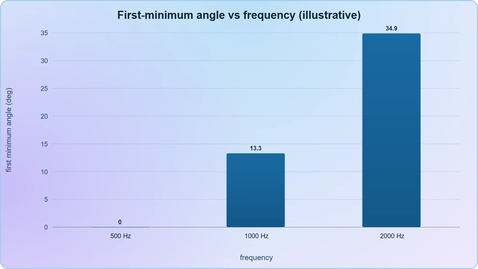
The comparison is instructive. Quadrupling the frequency from 500 Hz to 2000 Hz transforms an essentially non-directive aperture into one with a well-defined 35° lobe. The central maximum half-width, approximately ##\lambda/a## radians, falls from an undefined value to about 0.57 rad, or 33°. This scaling with ##1/f## is the acoustic analogue of beam narrowing in optics and is the reason high-frequency loudspeakers are physically small while subwoofers are large.
Students should note the arithmetic discipline required. The arcsine argument must lie within the interval from −1 to +1; if ##\lambda/a > 1##, no first minimum exists and the correct answer is that the pattern has no minimum in the forward direction. Examiners frequently set parameters that produce this outcome to test whether candidates apply the formula blindly or check its domain of validity first.
A second check concerns units. Wavelength must be expressed in the same unit as the aperture width, and the angle emerges in radians before conversion to degrees. Mixing millimetres and metres is the most common source of error in these calculations, and a quick dimensional audit before substitution eliminates it. The final answer should also be sanity-checked against the qualitative expectation that larger ##\lambda/a## means larger angle.
Diffraction, Interference, and the Limits of Distinguishability
Diffraction and interference are not separate phenomena but two descriptions of the same superposition mathematics. In a double-slit arrangement, each slit produces its own diffraction envelope, and the two envelopes interfere to produce fine fringes. The combined intensity is the product of the single-slit diffraction factor and the double-slit interference factor, so the fringes are modulated in brightness by the broader diffraction envelope.
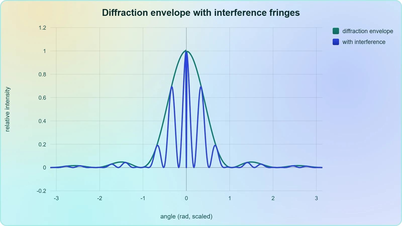
Here ##a## is the slit width and ##d## the slit separation. When ##d## is an integer multiple of ##a##, the interference maxima coincide with the diffraction minima and the corresponding fringes vanish, a condition known as a missing order. This coupling between the two scales is a favourite examination topic because it tests whether students understand that the envelope and the fringes have distinct physical origins.
The same mathematics underlies the resolution limit for sound detection. Two distant sources are resolvable only if their angular separation exceeds roughly ##\lambda/D##, where ##D## is the receiving aperture diameter. A large parabolic microphone therefore localises high-frequency sound far better than a small one, and the advantage grows linearly with aperture size and with frequency. This is the acoustic form of the Rayleigh criterion.
For JEE preparation, the essential takeaway is that the diffraction envelope sets the broad structure while interference sets the fine structure. Problems that ask for the number of fringes visible under the central diffraction maximum reduce to counting how many interference maxima fit between the first diffraction minima. The count depends only on the ratio ##d/a## and is independent of wavelength, a result worth memorising.
Applications: Barriers, Enclosures, and Audibility
Diffraction governs the performance of noise barriers along roads and railways. A barrier casts an acoustic shadow whose depth depends on the Fresnel number, which grows with barrier height, path-length difference, and frequency. Practical barriers achieve 10 to 15 dB of insertion loss in the mid-frequency band but considerably less at low frequencies, where diffraction over the top edge refills the shadow.
Within rooms, diffraction around furniture, columns, and open doorways redistributes sound energy and reduces the sharpness of geometric shadows. This is generally beneficial for speech intelligibility, since it prevents acoustic dead zones behind large objects. The next lesson on building acoustics takes up the complementary roles of reflection, absorption, and diffusion, and diffraction supplies the missing piece that explains why no room is truly silent behind a screen.
Underwater acoustics offers a striking illustration. Because the speed of sound in seawater is about 1500 m/s, a 100 Hz signal has a wavelength of 15 m, so it diffracts around submerged structures with ease and propagates to great distances. Sonar designers exploit this by choosing low frequencies for long-range detection and high frequencies, with their narrower beams, for precise localisation of nearby targets.
Medical ultrasound sits at the opposite extreme. At 5 MHz in tissue, with ##v \approx 1540## m/s, the wavelength is about 0.31 mm, so diffraction spreading is small and beams remain narrow over useful depths. The trade-off is unavoidable: higher frequency yields better resolution but greater attenuation, and the design of every imaging probe balances these competing requirements.
Problem-Solving Strategies and Examination Patterns
JEE questions on diffraction of sound cluster into a small number of recurring templates, and recognising the template is often worth more than lengthy algebra. The most frequent asks for the angle of the first minimum given frequency and aperture width, or conversely for the aperture width that places the first minimum at a specified angle. A second template compares audibility behind a barrier at two frequencies, and a third couples diffraction with interference in a double-slit configuration. Each template has a fixed sequence of steps that can be rehearsed until automatic.
Standard Problem Templates and Their Solution Sequences
The first template reduces to three operations: compute ##\lambda = v/f##, form the ratio ##\lambda/a##, and apply ##\sin\theta = \lambda/a## if the ratio is at most one. If the ratio exceeds one, the correct response is that no minimum exists. This domain check is the discriminating step that separates full marks from partial credit, and it should be performed before any trigonometric evaluation.
The second template requires a qualitative comparison supported by numbers. Compute the ratio ##\lambda/a## at each frequency and state which is larger; the larger ratio corresponds to greater spreading and therefore greater audibility in the shadow. Supporting the conclusion with the actual angles of the first minimum, where they exist, strengthens the answer and demonstrates command of the physics rather than mere recall.
The third template combines the diffraction envelope with the interference fringes. Identify the slit width ##a## and separation ##d##, compute the angular positions of the diffraction minima from ##\sin\theta = m\lambda/a##, and count the interference maxima from ##\sin\theta = n\lambda/d## that fall within the central envelope. The number of visible fringes is approximately ##2d/a - 1##, a compact result that saves considerable time under examination conditions.
A fourth, less common template involves Babinet's principle and asks for the pattern of a thin obstacle given the pattern of a slit of the same width. The minima positions are identical, and the central intensity differs because the obstacle transmits the unobstructed field minus the slit contribution. Recognising the complementarity immediately halves the work required.
Common Errors and How to Avoid Them
The most frequent error is applying the small-angle approximation outside its range. When ##\lambda/a## exceeds about 0.3, the difference between ##\theta## and ##\sin\theta## becomes material, and using the approximation can shift the answer by several degrees. Always evaluate the arcsine exactly when the ratio is large, and reserve the linear approximation for ratios below roughly 0.2.
A second error confuses the minima condition with the maxima condition. The minima satisfy ##a\sin\theta = m\lambda## with integer ##m##, while the secondary maxima lie approximately at half-integer multiples but not exactly. Students who assume exact half-integer maxima introduce small but avoidable inaccuracies, and examiners sometimes set options that punish this assumption.
A third error neglects the temperature dependence of the speed of sound. The speed in air varies as ##v \approx 331 + 0.6T## m/s with ##T## in degrees Celsius, so a change from 0 °C to 30 °C alters the wavelength by about five per cent. Unless the question specifies otherwise, 343 m/s at 20 °C is the standard value, but candidates should state the assumption explicitly when the temperature is given.
A fourth error misidentifies the relevant dimension. For a circular aperture the first minimum occurs at ##\sin\theta = 1.22\lambda/D##, not ##\lambda/D##, because of the geometry of the Airy pattern. Rectangular and circular apertures therefore require different constants, and questions that specify a circular loudspeaker or a circular detector expect the 1.22 factor.
Connecting Diffraction to the Wider Course
The preceding lesson established how sound reflects from surfaces and refracts through media with varying temperature or composition. Diffraction completes the trio of propagation phenomena by describing what happens when the wavefront is spatially truncated. Together, reflection, refraction, and diffraction account for essentially all of the large-scale behaviour of sound in realistic environments, and the next lesson applies all three to the design of auditoria.
In building acoustics, diffraction explains why sound reaches seats that have no direct line to the stage, why balconies cast softer shadows than their geometry suggests, and why low-frequency reverberation is difficult to control with modest absorptive panels. The wavelength-to-dimension ratio reappears as the organising principle, now applied to architectural features rather than laboratory slits. Students who internalise this ratio will find the next lesson largely a matter of application.
Beyond the syllabus, diffraction underpins technologies from sonar and medical imaging to noise-cancelling headphone design and architectural acoustics software. The same Fresnel-Kirchhoff framework that predicts the shadow of a highway barrier also predicts the beam profile of an ultrasound transducer. Recognising this unity is one of the intellectual rewards of studying wave phenomena systematically, and it is worth pausing to appreciate how far a single ratio can carry the analysis.
For revision, the essential facts are compact: minima at ##a\sin\theta = m\lambda##, central half-width approximately ##\lambda/a## radians, circular apertures with the 1.22 factor, and the rule that longer wavelength relative to aperture means greater spreading. Mastery of these four items, combined with disciplined unit handling and domain checks, covers the overwhelming majority of examination questions on this topic.
Also Read
- No links available.
From our network :
- Mastering DB2 LUW v12 Tables: A Comprehensive Technical GuideComprehensive guide on DB2 LUW v12 tables. Explore CREATE TABLE syntax, BLU Acceleration, range partitioning, data types, and security features for IBM DB2 LUW v12.
- EV 2.0: The Solid-State Battery Breakthrough and Global Factory ExpansionDiscover the impact of the Solid-State Battery Breakthrough on the EV market. Learn about CATL and BYD stock growth, global factory expansion in Europe, and the future of EV 2.0 technology.
- 98% of Global MBA Programs Now Prefer GRE Over GMAT Focus EditionExplore why 98% of global MBA programs now prefer the GRE over GMAT Focus. Learn about the shorter GRE format, verbal logic importance, and strategic versatility for students.
- Mastering DB2 12.1 Instance Design: A Technical Deep Dive into Modern Database ArchitectureComprehensive guide to DB2 12.1 Instance Design. Explore architectural components, HADR setup, buffer pool tuning, and security policies for IBM DB2 12.1. Includes 10 functional SQL and Shell samples.
- 10 Physics Numerical Problems with Solutions for IIT JEEPrepare for IIT JEE with 10 physics numerical problems, complete with detailed solutions and conceptual explanations. Ideal for mastering kinematics, thermodynamics, electromagnetism, and optics.
- Trump Political Strategy How Geopolitical Stunts Serve As Media Diversions
- AI-Powered 'Precision Diagnostic' Replaces Standard GRE Score ReportsDiscover the new GRE Precision Diagnostic. Learn how AI-powered behavioral analytics and time-to-solve tracking are replacing standard GRE score reports to empower students.
- Analyzing Trump Deportation Numbers Insights Into The 2026 Immigration Crackdown
- Vite 6/7 'Cold Start' Regression in Massive Module GraphsIn-depth analysis of Vite 6/7 cold start regressions in massive module graphs. Learn about barrel file issues, pre-bundling optimizations, and how to improve Vite dev server performance.
RESOURCES
- Diffraction of Sound - HyperPhysics Conceptshyperphysics.phy-astr.gsu.eduDiffraction in such cases helps the sound to "bend around" the obstacles. ... waves to bend around obstacles causes them to spread out past…
- Diffraction | ASCENDO IMMERSIVE AUDIOaia-cinema.comDiffraction refers to the phenomenon where sound waves bend around obstacles or spread as they pass through openings that are comparable in size to…
- Diffraction and interference conceptual physics answer key Tutorialwww2.american-usa.comDiffraction refers to the bending and spreading of waves as they pass through an opening or around an obstacle. This effect is more pronounced…
- What is Diffraction in Physics? Definition Diffraction is the bending ...facebook.comSep 27, 2026 ... ... Sound waves bending around buildings ... Diffraction vs Refraction Diffraction: Waves spread or bend around obstacles and through openings.
- What is Sound Diffraction? - AcousPlanacousplan.comMar 20, 2026 ... Sound diffraction is the bending of sound waves around obstacles and through openings. Learn how diffraction affects noise barriers, ...
- Understanding Sound Paths - Oeler Industries, Inc.oeler.com... wave, which then interacts with the structures around it through vibration ... Diffraction is the bending of sound waves around obstacles and through…
- 16.9 Wave Interactions - CK-12ck12.orgNov 1, 2012 ... ... sound waves spread out and travel around obstacles. This is called diffraction. It also occurs when waves pass through…
- Sound Diffraction: Waves & Causes | Vaiavaia.comOct 1, 2024 ... Sound diffraction is the bending and spreading of sound waves around obstacles and through openings, a phenomenon that is more…
- 10.2 Huygens's Principle: Diffraction - TEKS Guideteksguide.orgThe bending of a wave around the edges of an opening or an obstacle is called diffraction. ... diffraction occurs in all waves, including…
- Wave Interactions | CK-12 Foundationflexbooks.ck12.org... sound waves spread out and travel around obstacles. ... Diffraction occurs when waves spread out as they travel around obstacles or through openings…
- Huygens's Principle: Diffraction – Introductory Physics for the Health ...openbooks.lib.msu.edu... through a doorway while sound waves spread throughout ... Figure 80.6: Diffraction occurs when a wave passes through an opening or around an…
- Diffraction and Interference (Light) - Summaryphysics.infoLight diffracts through the opening or around the obstacle. An interference pattern arises from the interference of light waves from extreme ends of the…
- Reflection in Waves, Wave Refraction, and Diffraction - Albert.ioalbert.io... waves around barriers or through openings. This phenomenon allows waves to ... That is also thanks to the diffraction of radio waves around…
- Diffraction of sound - long versus short wavelengthsphysics.stackexchange.comJun 1, 2020 ... ... around a single edge rather than through a two-edged slit. ... wave propagation after hitting an object or passing…
- Interfaces and Barriers - Summary - The Physics Hypertextbookphysics.info(The wave is reflected out of phase.) Diffraction … is the bending or spreading of a wave around an obstacle or through an opening.…