
Navigating the formidable frontiers of orbital mechanics and human spaceflight requires an uncompromising commitment to aerodynamic precision and structural redundancy. As the Indian Space Research Organisation advances toward the realization of its maiden indigenous crewed orbital mission, every rigorous testing phase serves as an indispensable pillar of mission assurance. The recent triumphant execution of the secondary air drop test specifically targets the intricate dynamics of deceleration deployment systems under simulated atmospheric stress. Within this exacting domain of aerospace engineering, absolute safety margins must be empirically verified rather than theoretically assumed. Advanced mathematical modeling of supersonic deceleration profiles and ballistic descent trajectories provides the foundational framework for evaluating capsule recovery systems. Engineers must rigorously calculate atmospheric drag coefficients, kinetic energy dissipation rates, and thermal boundary layers experienced during re-entry phases. By subjecting prototype recovery assemblies to punishing drop tests from high-altitude platforms, the scientific collective gathers vital empirical telemetry. This methodical approach ensures that structural load limits are thoroughly understood and optimized for human-rated payloads.
On This Page
Aerodynamic Principles and Parachute Deployment Dynamics
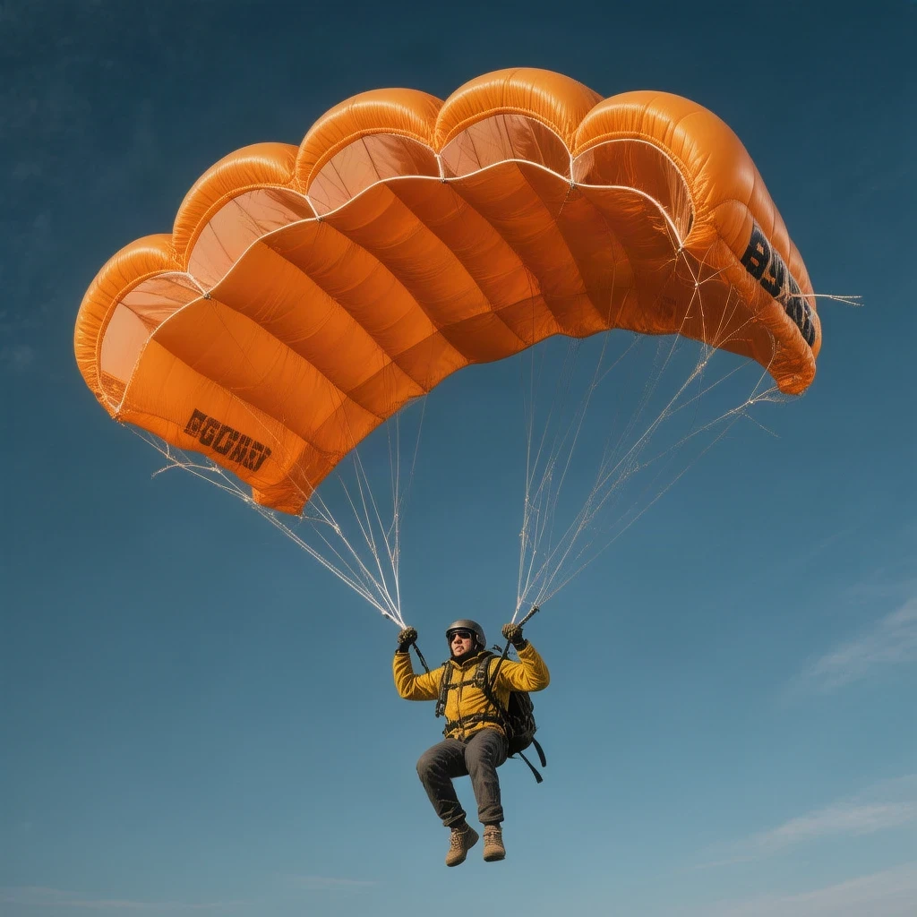
Understanding the intricate physics governing capsule recovery demands a profound examination of fluid dynamics and terminal velocity equations. When an orbital descent vehicle plunges back into dense atmospheric strata, kinetic energy must be shed rapidly to ensure occupant survival. The deployment sequence relies on a meticulously timed cascade of pilot chutes, drogue parachutes, and massive main canopy clusters. Each subsystem is engineered to withstand extreme dynamic pressure, commonly referred to in aerospace telemetry as ##[q]##, without suffering catastrophic structural failure.
Mathematical formulation of aerodynamic drag is vital for predicting deceleration behavior during descent phases. The net deceleration force depends heavily on air density, velocity, reference area, and the drag coefficient of the canopy assembly. Engineers utilize precise computational fluid dynamics simulations alongside empirical drop test data to refine these parameters. The fundamental drag equation governing this physical interaction is expressed in classical aerodynamic theory through rigorous analytical representations.
###[F_{d} = \dfrac{1}{2} \cdot \rho \cdot v^{2} \cdot C_{d} \cdot A]###
In this governing expression, ##[\rho]## represents the ambient atmospheric density at varying altitudes, ##[v]## denotes the instantaneous velocity of the descent capsule, ##[C_{dNOWLEDGE}]## or ##[C_{d}]## defines the dimensionless drag coefficient, and ##[A]## signifies the effective cross-sectional area of the deployed parachute canopy. Mastery over these variables allows flight dynamics specialists to predict deceleration profiles with remarkable accuracy.
Further analysis requires examining the time-dependent velocity decay as the parachute system opens fully. The acceleration of the falling mass relative to gravity and aerodynamic resistance can be structured as an initial value differential equation. Solving this system allows mission controllers to anticipate peak shock loads transferred to the structural harness of the crew module. The instantaneous vertical acceleration equation is established as follows.
###[\dfrac{dv}{dt} = g - \dfrac{\rho \cdot v^{2} \cdot C_{d} \cdot A}{2m}]###
Here, ##[m]## represents the total mass of the crew module and recovery rigging, while ##[g]## denotes the local acceleration due to gravity. Integrating this differential equation over the descent timeline yields precise velocity curves for every stage of atmospheric penetration. Such rigorous mathematical validation underpins the safety architecture of indigenous human spaceflight initiatives.
Engineering Safety Metrics and Redundancy Architecture

Ensuring absolute human-rating compliance mandates building multi-layered redundancy into every critical subsystem of the Gaganyaan vehicle. Parachute deployment architectures cannot rely upon single points of failure, prompting engineers to incorporate dual-redundant deployment mortars and independent pyrotechnic trigger circuits. Each redundant channel undergoes extensive environmental screening, including thermal vacuum testing and vibration profiling, to guarantee fail-safe operational readiness in orbit.
Quantitative risk assessment models are heavily utilized to calculate cumulative failure probabilities across all descent sequences. By combining component reliability metrics with environmental variance factors, statistical analysts determine whether the overall mission architecture meets stringent international spaceflight standards. The composite reliability probability ##[R_{total}]## for parallel redundant parachute release systems is mathematically modeled through standard reliability equations.
###[R_{total} = 1 - \prod_{i=1}^{n} (1 - R_{i})]###
Within this formulation, ##[R_{i}]## represents the operational reliability of the ##[i]##-th independent deployment mechanism, and ##[n]## denotes the total count of redundant subsystems. Implementing dual or triple redundancy pushes the cumulative reliability value exceptionally close to unity, satisfying the stringent safety benchmarks required for crewed space exploration.
In addition to reliability mathematics, thermal dissipation during atmospheric deceleration demands sophisticated materials engineering. Parachute canopies are fabricated from high-tensile synthetic fibers such as Kevlar and advanced polyamide blends capable of maintaining structural integrity under intense frictional heating. The total heat energy ##[Q]## absorbed by the descending capsule can be evaluated through the integration of aerodynamic heating flux over the descent duration.
###[Q = \int_{0}^{t} \dot{q}_{aer} (t) \cdot A_{s} \, dt]###
In this energy equation, ##[\dot{q}_{aer}(t)]## denotes the transient heat flux per unit area, and ##[A_{s}]## represents the effective surface area exposed to atmospheric compression. Maintaining strict control over these thermal parameters guarantees that internal cabin temperatures remain within survivable limits for the crew throughout the recovery process.
We Also Published
Strategic Implications for India's Indigenous Space Program
The successful execution of successive drop tests represents a monumental leap forward for India's strategic standing in global space exploration. Achieving complete indigenous capability in human-rated capsule design and recovery ensures national technological sovereignty and opens new horizons for commercial aerospace partnerships. As ISRO transitions from unmanned robotic missions to complex crewed orbital flights, the meticulous validation of recovery systems sets a benchmark for engineering excellence.
Analyzing the long-term economic and scientific dividends of human spaceflight requires factoring in technological spillover effects across domestic industries. Precision manufacturing, advanced metallurgy, and aerospace electronics developed during the Gaganyaan program inevitably invigorate broader manufacturing sectors. The return on investment for such high-complexity scientific endeavors extends far beyond orbital milestones, fostering a vibrant ecosystem of technological innovation nationwide.
From our network :
- Mastering DB2 LUW v12 Tables: A Comprehensive Technical GuideComprehensive guide on DB2 LUW v12 tables. Explore CREATE TABLE syntax, BLU Acceleration, range partitioning, data types, and security features for IBM DB2 LUW v12.
- Vite 6/7 'Cold Start' Regression in Massive Module GraphsIn-depth analysis of Vite 6/7 cold start regressions in massive module graphs. Learn about barrel file issues, pre-bundling optimizations, and how to improve Vite dev server performance.
- Mastering DB2 12.1 Instance Design: A Technical Deep Dive into Modern Database ArchitectureComprehensive guide to DB2 12.1 Instance Design. Explore architectural components, HADR setup, buffer pool tuning, and security policies for IBM DB2 12.1. Includes 10 functional SQL and Shell samples.
- Analyzing Trump Deportation Numbers Insights Into The 2026 Immigration Crackdown
- 98% of Global MBA Programs Now Prefer GRE Over GMAT Focus EditionExplore why 98% of global MBA programs now prefer the GRE over GMAT Focus. Learn about the shorter GRE format, verbal logic importance, and strategic versatility for students.
- 10 Physics Numerical Problems with Solutions for IIT JEEPrepare for IIT JEE with 10 physics numerical problems, complete with detailed solutions and conceptual explanations. Ideal for mastering kinematics, thermodynamics, electromagnetism, and optics.
- AI-Powered 'Precision Diagnostic' Replaces Standard GRE Score ReportsDiscover the new GRE Precision Diagnostic. Learn how AI-powered behavioral analytics and time-to-solve tracking are replacing standard GRE score reports to empower students.
- EV 2.0: The Solid-State Battery Breakthrough and Global Factory ExpansionDiscover the impact of the Solid-State Battery Breakthrough on the EV market. Learn about CATL and BYD stock growth, global factory expansion in Europe, and the future of EV 2.0 technology.
- Trump Political Strategy How Geopolitical Stunts Serve As Media Diversions
RESOURCES
- ISRO conducts Second Integrated Air Drop Test (IADT-02) for ...isro.gov.inThe second Integrated Air Drop Test (IADT-02) for Gaganyaan mission was successfully conducted at Satish Dhawan Space Centre, Sriharikota on April 10, 2026. In ...
- Bustec Supports ISRO's Gaganyaan Mission Ground Test Systems ...bustec.comNov 5, 2025 ... Bustec will supply LXI-based data acquisition and test systems for ISRO's 2027 Gaganyaan human spaceflight program — ensuring accuracy, ...
- Successful accomplishment of key development test in ... - ISROisro.gov.inNov 11, 2025 ... ISRO has successfully conducted an important test on Main Parachutes for the Gaganyaan Crew Module at the Babina Field Firing…
- Gaganyaan-1 - Wikipediaen.wikipedia.orgGaganyaan-1 is the first planned uncrewed test flight of the Gaganyaan programme. ISRO has officially scheduled the mission for Q4 2026. Gaganyaan-1 ...
- Gaganyaan mission: Isro chairman hints first uncrewed test flight ...reddit.comJun 30, 2026 ... Gaganyaan G1 mission has received clearance from National Review Committee in early May 2026, launch is expected in three to…
- ISRO successfully carries out tests of Gaganyaan crew module ...thehindu.comJul 12, 2026 ... ISRO successfully tests Gaganyaan crew module systems, ensuring astronaut safety and structural integrity for future space missions.
- Gaganyaan - Wikipediaen.wikipedia.orgGaganyaan crew-module mounted on TV-D1 vehicle, in-preparations towards a sub-orbital test flight. Manufacturer. ISRO · DRDO · HAL. Country of origin, India.
- India launches test flight ahead of sending crew into space - BBCbbc.comOct 20, 2023 ... Isro The Gaganyaan mock up flight at the launch pad in Sriharikota · Isro Vyommitra is a female humanoid built…




0 Comments