On This Page
Introduction to Precision Instruments
Precision instruments are fundamental tools in experimental physics, enabling us to measure physical quantities far more accurately than standard rulers or scales. These devices are designed to minimize observational errors and provide readings with higher resolution, which is crucial for verifying theoretical predictions and conducting reliable scientific investigations. Understanding their operation is a cornerstone for any aspiring physicist or engineer.
The ability to use these instruments correctly is not just a practical skill but a conceptual one, reinforcing the idea that physics is an empirical science built on careful observation. Without precise measurement, differentiating between closely related phenomena or validating subtle physical effects becomes impossible. This foundational knowledge supports all subsequent experimental work in your JEE and NEET preparation.
Standard measuring tools like rulers often have a least count of 1 millimeter (mm), which is sufficient for many everyday tasks but inadequate for situations demanding greater accuracy. For instance, measuring the diameter of a thin wire or the thickness of a small plate requires instruments that can resolve dimensions down to fractions of a millimeter. This is where Vernier calipers and screw gauges become indispensable.
These instruments extend the capabilities of basic measurements by incorporating ingenious mechanisms that allow for finer subdivisions of the smallest main scale division. By mastering their use, you gain a significant advantage in laboratory practicals and problem-solving scenarios. It also cultivates an appreciation for the engineering behind scientific tools and their impact on scientific progress.
The precision offered by Vernier calipers and screw gauges directly influences the reliability of experimental data. In examinations like JEE and NEET, problems often test your understanding of how these instruments work, including their limitations and error correction. Therefore, a thorough grasp of their principles and practical application is absolutely essential for success.
The Concept of Least Count
The least count of a measuring instrument represents the smallest measurement it can accurately resolve. It quantifies the precision of the device, indicating the minimum observable change in the quantity being measured. For any instrument, the least count sets the limit for how finely we can distinguish between two very close readings, directly impacting the quality of our experimental data.
For instruments like Vernier calipers and screw gauges, the least count is not simply the smallest division on the main scale. Instead, it results from the difference between one main scale division (MSD) and one Vernier scale division (VSD), or between the pitch and the circular scale divisions. This calculated value is critical for determining the resolution of the instrument.
Calculating the least count is a straightforward process, but it requires careful attention to the scales involved. For a Vernier caliper, it is typically the difference between one main scale division and one Vernier scale division. For a screw gauge, it involves the pitch of the screw and the number of divisions on its circular scale.
\text{Least Count (LC)} = 1 \text{ MSD} - 1 \text{ VSD} \\
\text{Alternatively, if } n \text{ VSD} = (n-1) \text{ MSD}, \text{ then } 1 \text{ VSD} = \dfrac{(n-1)}{n} \text{ MSD} \\
\text{So, LC} = 1 \text{ MSD} - \dfrac{(n-1)}{n} \text{ MSD} = \dfrac{1}{n} \text{ MSD}
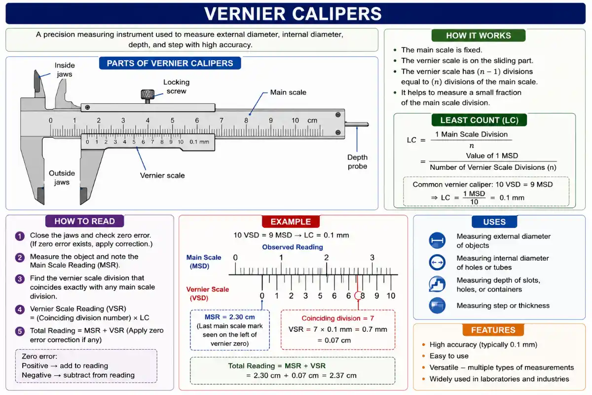
Vernier Caliper Reading
This formula combines the coarser main scale reading with the finer Vernier scale reading to produce a complete and precise measurement. It is the fundamental equation for using Vernier calipers effectively in any experimental setup or problem-solving scenario.
Mastering the Vernier caliper involves not just reading the scales but also understanding how to properly handle the instrument to avoid parallax errors and ensure the jaws are firmly but gently gripping the object. Practice with real instruments is invaluable for developing this proficiency, which is vital for practical examinations and laboratory work.
Reading the Vernier Scale
Reading the Vernier scale correctly is the most critical step in using Vernier calipers for accurate measurements. After noting the main scale reading (MSR), which is the last complete main scale division before the Vernier scale's zero mark, your focus shifts to the Vernier scale itself. This is where the instrument's enhanced precision comes into play.
You must carefully observe which division on the Vernier scale precisely aligns or coincides with any division on the main scale. This aligned mark is the Vernier Scale Coincidence (VSC). It’s crucial to select the single best match, as sometimes multiple lines might appear close, but only one will be perfectly aligned.
Once you have identified the VSC, you multiply this number by the least count of the Vernier caliper. This product represents the fractional part of your total measurement, extending the precision beyond what the main scale alone can offer. For example, if the VSC is 7 and the LC is 0.01 cm, the fractional part is 0.07 cm.
Combining the MSR and the calculated fractional part gives you the observed reading. For instance, if MSR is 2.5 cm and the fractional part is 0.07 cm, the observed reading is 2.57 cm. This systematic approach ensures that you extract the maximum possible information from the instrument.
Students often make mistakes by misidentifying the VSC or by incorrectly applying the least count. Consistent practice with various examples and direct instrument use is the best way to develop accuracy and confidence in reading Vernier calipers, a skill frequently tested in JEE and NEET practical physics sections.
Identifying and Correcting Zero Error in Vernier Calipers
Zero error is a systematic error inherent in many measuring instruments, including Vernier calipers, which occurs when the instrument does not read exactly zero when it should. For Vernier calipers, this happens when the jaws are closed completely, and the zero mark of the Vernier scale does not perfectly align with the zero mark of the main scale.
There are two types of zero error: positive and negative. A positive zero error occurs when the Vernier scale zero is to the right of the main scale zero when the jaws are closed. This means the instrument is reading a small positive value even when the actual measurement is zero, leading to inflated readings.
To determine positive zero error, close the jaws and note the Vernier scale division that coincides with a main scale division. Multiply this coincidence by the least count. If the Vernier zero is to the right, the error is positive. For example, if the 5th VSD coincides and LC is 0.01 cm, the positive zero error is ##+0.05 \text{ cm}##.
A negative zero error occurs when the Vernier scale zero is to the left of the main scale zero. In this case, the instrument reads a small negative value when it should be zero. To calculate negative zero error, find the VSD that coincides, but count it from the right end of the Vernier scale (or subtract from total divisions).
The correction for zero error is always subtracted from the observed reading. So, ##\text{Corrected Reading} = \text{Observed Reading} - \text{Zero Error}##. If the zero error is negative, subtracting a negative value effectively adds it. This crucial step ensures that your final measurement accurately reflects the true dimension of the object.
Working with the Screw Gauge
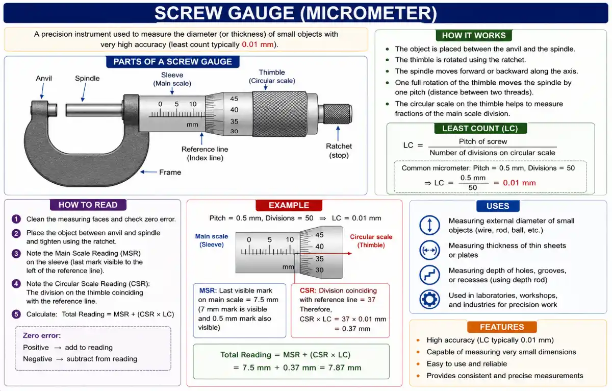
The screw gauge is an even more precise measuring instrument than the Vernier caliper, capable of measuring dimensions typically down to 0.01 mm or 0.001 cm. It operates on the principle of a screw, where a rotational movement of a thimble translates into a very small linear movement of a spindle. This mechanism allows for extremely fine measurements.
It consists of a U-shaped frame, a main scale (pitch scale) along a fixed sleeve, and a circular scale (thimble scale) that rotates. The object to be measured is placed between the anvil and the spindle, and the thimble is rotated until the object is gently gripped. The ratchet stop ensures consistent pressure, preventing over-tightening.
The main scale, or pitch scale, is typically graduated in millimeters. As the thimble completes one full rotation, the spindle moves a fixed distance along the main scale. This distance is called the "pitch" of the screw, which is usually 0.5 mm or 1 mm, representing the linear distance moved for one full rotation.
The circular scale is divided into 50 or 100 divisions. The least count of the screw gauge is determined by dividing the pitch by the total number of divisions on the circular scale. This value represents the smallest linear distance that can be measured by rotating the circular scale by one division.
\text{Least Count (LC)} = \dfrac{\text{Pitch}}{\text{Number of divisions on circular scale}} \\
\text{If Pitch} = 1 \text{ mm} \text{ and Circular Divisions} = 100, \text{ then LC} = \dfrac{1 \text{ mm}}{100} = 0.01 \text{ mm} = 0.001 \text{ cm}
Screw Gauge Reading
This formula is the cornerstone for accurately using a screw gauge. Understanding each component and applying them correctly is vital for obtaining reliable measurements in experiments and solving related problems in competitive exams.
Proper handling, including gentle tightening with the ratchet, is crucial to prevent deformation of the object or damage to the instrument. Always ensure the object is placed squarely between the anvil and spindle for an accurate measurement. Practicing these techniques is key to mastering the screw gauge.
Zero Error and Backlash in Screw Gauge
Similar to Vernier calipers, screw gauges can exhibit zero error. A positive zero error occurs when the zero mark of the circular scale is below the main line of the pitch scale when the anvil and spindle are in contact (jaws closed). This means the instrument reads a positive value when it should be zero.
To calculate positive zero error, note the circular scale division that coincides with the main line when the jaws are closed. Multiply this coincidence by the least count. If the zero of the circular scale is below the main line, the error is positive. For example, if the 3rd CSD coincides and LC is 0.01 mm, the positive zero error is ##+0.03 \text{ mm}##.
A negative zero error occurs when the zero mark of the circular scale is above the main line when the jaws are closed. In this case, the instrument reads a small negative value. To find negative zero error, count the coinciding CSD from the total number of divisions backwards (e.g., if total 100 divisions, and 97th coincides, then ##(100-97) \times \text{LC}##).
Another type of error specific to screw gauges is backlash error. This occurs due to wear and tear in the screw and nut mechanism, leading to a slight play. When the direction of rotation of the thimble is reversed, the spindle does not immediately change its direction of motion; there is a small delay or 'slack'.
Backlash error can affect measurements if the thimble is rotated back and forth during a reading. To minimize its effect, always approach the final tightening position by rotating the thimble in one consistent direction, typically clockwise. This ensures that the screw mechanism is always engaged in the same manner, leading to more consistent and accurate readings.
Practical Applications and Error Analysis
Mastering Vernier calipers and screw gauges is not just about taking readings; it's about understanding and applying error analysis to ensure the reliability of your experimental data. The final corrected reading is derived by systematically accounting for the instrument's inherent limitations and any observed zero errors. This methodical approach is critical for scientific accuracy.
The principles of least count, zero error, and correction are fundamental across various branches of physics. From determining the density of a material by measuring its dimensions and mass, to calculating Young's modulus of a wire, precise length measurements are always required. These instruments provide the necessary foundation for such experiments.
In examinations like JEE Main, JEE Advanced, and NEET, questions frequently involve scenarios where students must apply these concepts to calculate unknown quantities or identify correct experimental procedures. These problems test both your conceptual understanding and your ability to perform accurate calculations under exam pressure.
A common mistake students make is neglecting to correct for zero error, which can lead to consistently inaccurate results. Another pitfall is incorrectly identifying the least count or misinterpreting the coinciding divisions on the scales. Developing a systematic approach to reading and correcting measurements will help avoid these errors.
Therefore, a strong grasp of these instruments and their associated error analysis is indispensable. It not only prepares you for practical components of your curriculum but also hones your analytical skills, which are transferable to many other areas of physics and beyond. Precision in measurement equals precision in understanding.
Deriving Corrected Readings
The process of deriving a corrected reading is a crucial step that transforms an observed measurement into a scientifically valid value. It directly addresses the systematic errors introduced by the instrument itself, primarily the zero error. This correction ensures that the final reported value is as close as possible to the true physical dimension.
First, obtain the observed reading using the appropriate formula for either the Vernier caliper or the screw gauge. This involves combining the main scale reading with the product of the coinciding division and the instrument's least count. This observed reading is your raw data before any adjustments for instrumental bias.
Next, carefully determine the zero error of the instrument. This step must be performed before taking any actual measurements, by bringing the jaws or spindle into contact. Identify whether the error is positive or negative, and calculate its magnitude using the least count and the appropriate coinciding division.
The formula for the corrected reading is universal: ##\text{Corrected Reading} = \text{Observed Reading} - \text{Zero Error}##. It is important to remember that if the zero error itself is negative, subtracting a negative value will result in an addition to the observed reading, effectively compensating for the instrument reading too low.
Consider a Vernier caliper where the observed reading for an object is 3.45 cm. If the instrument has a positive zero error of ##+0.02 \text{ cm}##, the corrected reading would be ##3.45 \text{ cm} - (+0.02 \text{ cm}) = 3.43 \text{ cm}##. If the zero error was ##-0.03 \text{ cm}##, the corrected reading would be ##3.45 \text{ cm} - (-0.03 \text{ cm}) = 3.48 \text{ cm}##.
| Zero Error Type | Appearance (Jaws Closed) | Calculation | Correction Applied |
|---|---|---|---|
| Positive Zero Error | Vernier/Circular Zero is right/below Main Scale Zero | ##\text{VSC/CSC} \times \text{LC}## (positive value) | Subtract from observed reading |
| Negative Zero Error | Vernier/Circular Zero is left/above Main Scale Zero | ##-( \text{Total Divisions} - \text{VSC/CSC}) \times \text{LC}## (negative value) | Add to observed reading (subtracting a negative) |
JEE/NEET Relevance and Common Pitfalls
For JEE and NEET examinations, questions on Vernier calipers and screw gauges are common, often appearing in the form of direct calculations, conceptual understanding of errors, or practical scenario-based problems. These questions assess your ability to apply the learned principles under varying conditions and time constraints.
One frequent question type involves calculating the least count of an instrument given its scale divisions, or using a provided least count to find a measurement. Another popular pattern is to present an observed reading along with a zero error, requiring you to determine the final corrected value accurately.
Students often confuse positive and negative zero errors, leading to incorrect corrections. Remember: a positive zero error means the instrument reads *more* than it should, so you *subtract* it. A negative zero error means it reads *less* than it should, so you *add* its magnitude to compensate.
| Pitfall | Description | Impact on Result |
|---|---|---|
| Incorrect Least Count | Miscalculation or memorization error of LC. | All readings will be incorrect; precision misjudged. |
| Ignoring Zero Error | Failing to check for and apply zero correction. | Systematic bias in all measurements (inaccurate). |
| Parallax Error | Viewing scales from an angle, not perpendicularly. | Apparent shift in reading, leading to inaccuracy. |
| Improper Handling | Over-tightening screw gauge, loose Vernier jaws. | Deforms object, damages instrument, inconsistent readings. |
Furthermore, questions might involve scenarios where you need to identify the correct Vernier or circular scale coincidence from a diagram, or even deduce the pitch of a screw gauge from given information. These require a solid visual and conceptual understanding, not just rote memorization of formulas.
A strong foundation in using these instruments and understanding their errors is not only vital for scoring well in these specific question types but also for building robust experimental skills crucial for higher studies in science and engineering. Practice solving a diverse range of problems to solidify your understanding.
RESOURCES
- JEE 2025 - Clarity in Zero Error | Vernier & Screw Gauge - YouTubeyoutube.comDec 26, 2022 ... Download Vernier & Screw Gauge 1 Page Formulae Sheet - https://telegram.me/edunitimg/1545 Download Modern Physics 2 Page Formulae Sheet ...
- Vernier Calipers and Screw Gaugesimply.scienceIf the zero mark on the circular scale is below the base line of the main scale, the error is said to be positive.…
- Labworld Vernier Caliper+Screw Gauge 25mm combo pack of 2 ...amazon.inLabworld Vernier Caliper+Screw Gauge 25mm combo pack of 2 Micrometer Slide 12.5cm metallic for Measurement of Round Objects and depth used in Industrial ...
- Understanding Zero Error in Vernier Calipers | PDF | Metrology | Toolsscribd.comZero Error in Micrometer. Problem 1: Problem 2: The pitch of a screw gauge is 1 mm and there are 50 divisions on its…
- Problems On Vernier Calipers and Screw Gauge | PDF - Scribdscribd.comThe Vernier scale of the other caliper (C2) has 10 equal divisions that correspond to 11 main scale divisions. The readings of the two…
- Worksheet ( Vernier Calipers / Micrometer Screw Gauge )scientistkearns.weebly.comWorksheet ( Vernier Calipers / Micrometer Screw Gauge ). Page 2. Page 3. Page 4. Page 5. Page 6. Page 7. Worksheet ( Vernier…
- Screw Gauge Simulator — 0.01 mm Precision - MechSimulatormechsimulator.comMar 20, 2026 ... Defines the permissible maximum errors at each ... If you found this Micrometer Screw Gauge simulator helpful, explore our Vernier…
- Vernier Calipers And Micrometer Screw Gauges, Measuring Without ...hackaday.comJun 8, 2020 ... It has a 0.01 mm resolution, but given the not-entirely-flat jaws and the play in the thread I would be…
- screw gauge measures more accurately than vernier callipers ... - Vaiavaia.comA screw gauge has a tighter pitch and a finer scale than a vernier calliper, which allows it to read measurements with more decimal…
- Solved Worksheet (Vernier Calipers / Micrometer Screw Gaugechegg.comMay 10, 2022 ... Vernier Calipers A. The following calipers have no zero errors. Determine the actual readings on each caliper : 1 a)…
- Zero error in Vernier Callipers & Screw Guage - Physics Practicalsphysicsguideline.blogspot.comZero error in vernier Calipers: Errors are produced in an instrument due to ... Zero error in Screw Gauge: Positive Zero Error: If the…
- Solved (b) 0.001 (c) 0.1 (d) 0.01 36 vernier calipers and a - Cheggchegg.comJun 13, 2019 ... Question: (b) 0.001 (c) 0.1 (d) 0.01 36 vernier calipers and a screw gauge have the same east count and…
- Quick Guide to Precision Measuring Instruments - Mitutoyomitutoyo.comMajor Measurement Errors of the Screw Micrometer. Supporting method. Supported ... Some early calipers divided 19 divisions on the main scale by 20 vernier.
- : Units & Measurement in Physicsp3physics.comApply dimensional analysis to verify equations and solve problems. Use Vernier Calipers and Screw Gauge accurately for experimental measurements. Identify and ...
- Vernier Callipers JEE Problems with Solutions - Exam Secretsexaminationsecrets.wordpress.comApr 28, 2017 ... Screw Gauge JEE Problems with Solutions. 31 thoughts on “Vernier ... When external diameter is measured with calipers,vernier zero lies…