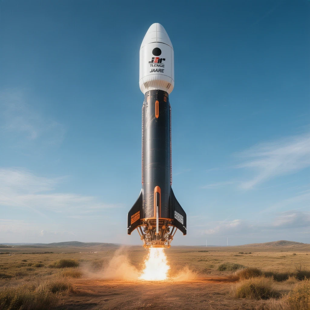
The emergence of commercial aerospace enterprises within the People’s Republic of China signifies a monumental paradigm shift in global orbital mechanics and geopolitical dominance. Private aerospace manufacturers are rapidly challenging state-run monopolies through aggressive iterative engineering, aiming to match and surpass Western reusable launch capabilities. At the forefront of this commercial revolution stands LandSpace, an elite private venture engineering advanced methane-liquid oxygen launch systems designed for rapid turnaround. The scheduled August 10, 2026, flight test of the Zhuque-3 rocket represents not merely a corporate milestone, but a critical geopolitical indicator of China’s expanding industrial capacity in orbital transportation.
Understanding the rigorous aerodynamic and thermodynamic complexities governing modern reusable launch vehicles requires a deep analysis of propellant mass fractions and atmospheric entry physics. When evaluating the structural integrity of stainless steel versus carbon composite airframes during supersonic retropropulsion, mathematical modeling provides definitive insights into structural load limits. The engineering triumphs achieved by LandSpace underscore a broader systemic evolution in how modern nation-states leverage private capital and agile corporate structures to accelerate aerospace innovation.
On This Page
Propulsion Dynamics and Methane-Oxygen Thermodynamics
The transition toward liquid oxygen and liquid methane propellant architectures marks a profound technological evolution in modern rocket propulsion. Methane combustion yields significantly lower soot formation compared to traditional kerosene alternatives, drastically reducing coking within the combustion chamber and turbine turbopumps. This clean-burning characteristic is essential for achieving the high operational reuse frequencies mandated by modern economic models in commercial spaceflight.
Combustion Efficiency and Chamber Pressures
Engineers optimize thrust-to-weight ratios by precisely calculating chamber pressures and mass flow rates through complex nozzle geometries. The theoretical performance of the Zhuque-3’s primary engines can be evaluated by examining the specific impulse ##[I_{sp}]## under varying atmospheric expansion ratios.
###[I_{sp} = \dfrac{F}{\dot{m} g_0} = \dfrac{c_g}{g_0} \sqrt{\dfrac{2\gamma}{\gamma – 1} \left( 1 – \left( \dfrac{P_e}{P_c} \right)^{\frac{\gamma – 1}{\gamma}} \right)} + \dfrac{(P_e – P_a)A_e}{\dot{m} g_0}###
Through rigorous thermodynamic iteration, propulsion teams ensure that exit pressures ##[P_e]## closely match ambient atmospheric pressure ##[P_a]## to prevent flow separation and thrust degradation during ascent. This meticulous optimization directly impacts payload capacity to low Earth orbit.
Thermal Management
During Re-EntryThermal protection systems must endure extreme heat fluxes generated during atmospheric deceleration. The convective heat transfer rate ##[q]## is fundamentally tied to the density and velocity profile of the surrounding shock layer.
###[q = C \sqrt{\rho_e} V_e^3]###
Advanced cooling channels integrated directly into the engine bell structure circulate sub-cooled liquid methane to absorb thermal energy before injection. This regenerative cooling loop prevents material failure under sustained operational loads.
Aerodynamic Trajectory and Guidance Control
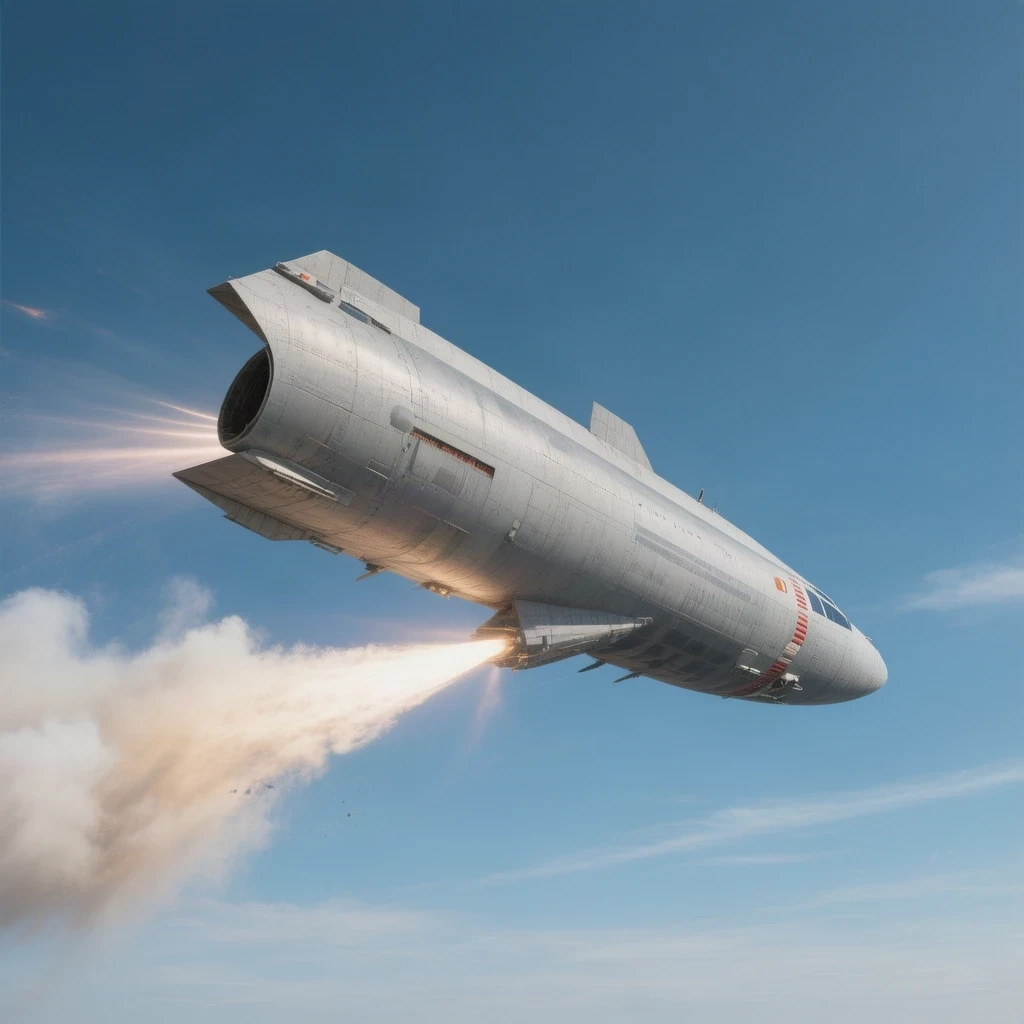
Guiding a massive orbital booster back to a precise landing pad requires sophisticated guidance algorithms operating in real time. The descent profile must account for unpredictable high-altitude wind shear and atmospheric density variations. Control moment gyroscopes and grid fins work in tandem to manipulate the vehicle’s angle of attack throughout hypersonic deceleration.
Descent Kinematics and Drag Optimization
The deceleration profile depends heavily on the ballistic coefficient ##[\beta]##, which dictates how rapidly the vehicle sheds velocity in the upper atmosphere. Engineers model this trajectory using fundamental kinematic equations adapted for variable gravity fields.
###[m \dfrac{dV}{dt} = -D – mg \sin(\gamma) + F_{\text{thrust}}]###
By modulating aerodynamic lift and drag through controlled bank angles, onboard flight computers ensure the booster stays within safe load factor boundaries ##[n \le 5g]##.




0 Comments