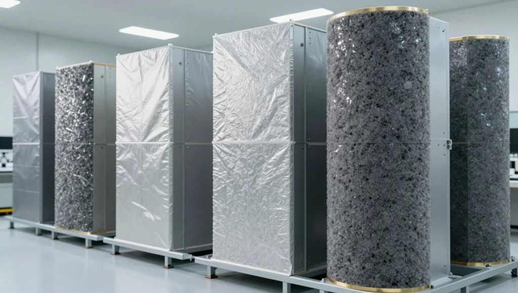
Neutron radiation occupies a peculiar position within the broader landscape of ionizing radiation safety, because the very properties that make neutrons valuable in medicine, research, and energy production also make them extraordinarily difficult to contain. Unlike alpha particles, which a sheet of paper halts, or gamma rays, which dense lead attenuates effectively, neutrons carry no electric charge and therefore ignore the electromagnetic barriers that dominate conventional shielding design. Facilities that generate neutron fields—reactors, cyclotrons, spallation sources, radiotherapy bunkers—must therefore reason from nuclear physics rather than from familiar radiological habits, treating shielding as a problem of scattering, moderation, and capture rather than simple absorption.
The central insight governing neutron protection is that fast neutrons must first be slowed before they can be absorbed efficiently. Hydrogen-rich materials accomplish this moderation because a neutron colliding with a proton of nearly identical mass transfers a large fraction of its kinetic energy in a single encounter. Once thermalized, neutrons become far more susceptible to capture reactions, particularly the ##[^{10}\text{B}(n,\alpha)^{7}\text{Li}]## and ##[^{1}\text{H}(n,\gamma)^{2}\text{H}]## processes that convert dangerous free neutrons into stable products or secondary gamma radiation that must itself be managed. This two-stage logic—moderate, then capture—underpins virtually every engineered shield in operation today.
Understanding neutron shielding also requires appreciating the secondary hazards that shielding itself can create. Capture gamma rays, activation products in structural materials, and the residual dose fields around thick concrete walls all demand careful design and continuous monitoring. The following analysis examines how neutron radiation is produced, why it defeats conventional barriers, which materials actually work, and how facilities integrate physics, engineering, and regulatory discipline into a coherent safety culture that protects workers and the public alike.
On This Page
- The Physical Origins of Neutron Radiation
- Why Neutrons Defeat Conventional Shielding
- Moderation: The First Essential Step
- Absorption and Capture Reactions
- Composite Shielding Design in Practice
- Monitoring, Dosimetry, and Operational Safety
- Emerging Materials and Future Directions
- Worked Calculations for Neutron Attenuation
The Physical Origins of Neutron Radiation
Neutron radiation arises whenever nuclear transformations release unbound neutrons, and the diversity of these sources shapes how facilities plan their protection strategies. Each source type produces a characteristic energy spectrum, and that spectrum determines which moderators and absorbers will prove effective in practice.
Fission and Spallation Sources
Nuclear fission releases roughly two to three neutrons per event, with a fission spectrum peaking near ##[2\ \text{MeV}]## and extending beyond ##[10\ \text{MeV}]##. Reactor cores therefore represent intense, continuous neutron fields requiring deep biological shielding. Spallation sources accelerate protons into heavy targets, generating pulsed neutron bursts of far higher energy that demand specialized moderation before experimental use.
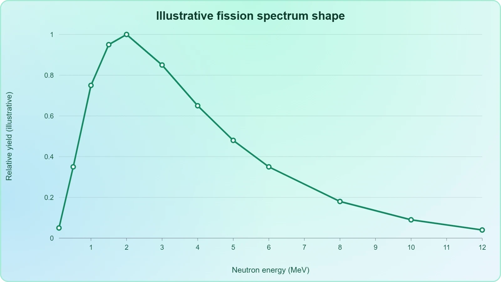
Research reactors and accelerator facilities publish detailed neutron spectra so that shield designers can model attenuation accurately. The energy distribution matters enormously: a shield optimized for thermal neutrons may perform poorly against the fast component, and vice versa. Facilities therefore characterize their sources empirically and validate computational models against measured dose rates.
Radioisotope and Fusion Neutron Emitters
Compact sources such as americium-beryllium or californium-252 mixtures produce neutrons through alpha-induced reactions, offering portable fields for calibration and industrial gauging. Deuterium-tritium fusion generators emit nearly monoenergetic ##[14.1\ \text{MeV}]## neutrons, among the most penetrating routinely encountered in laboratory settings. Each source demands tailored shielding geometry and monitoring.
Medical cyclotrons that produce positron-emitting radiopharmaceuticals generate secondary neutron fields during target irradiation, a hazard often underestimated in clinical environments. Facilities must therefore treat neutron protection as a routine operational concern rather than an exotic specialty confined to national laboratories and power stations.
Why Neutrons Defeat Conventional Shielding
The absence of electric charge fundamentally changes how neutrons interact with matter, invalidating the intuition that heavier and denser materials always shield better. Understanding this distinction is essential before selecting any barrier material.
The Coulomb Barrier Problem
Charged particles lose energy continuously through Coulomb interactions with atomic electrons, so dense high-Z materials like lead excel at stopping them. Neutrons experience no such force and interact only through short-range nuclear collisions, meaning they can traverse meters of lead with only occasional scattering events. Density alone offers little protection.
This is why a lead apron that stops diagnostic X-rays provides essentially no neutron shielding. The interaction probability depends on nuclear cross-sections rather than electron density, and for many elements those cross-sections remain small across the fast neutron energy range. Designers must therefore abandon density-based reasoning entirely.
Penetration, Scattering, and Skyshine
Fast neutrons undergo elastic and inelastic scattering, gradually losing energy while changing direction, and this scattering can transport radiation around corners and through maze entrances. The phenomenon of skyshine—neutrons scattering off the atmosphere and returning to ground level—extends dose fields well beyond direct line of sight.
Facilities must therefore model scattered radiation, not merely direct beams, when designing walls and calculating boundary dose rates. A shield that blocks the direct path may still permit unacceptable doses through scatter, and regulatory compliance depends on accounting for these indirect pathways with conservative margins.
Moderation: The First Essential Step
Because fast neutrons resist capture, effective shielding begins with slowing them to thermal energies where absorption cross-sections become substantial. Moderation exploits elastic collisions with light nuclei, and the kinematics of those collisions determine which materials perform best.
Kinematics of Elastic Scattering
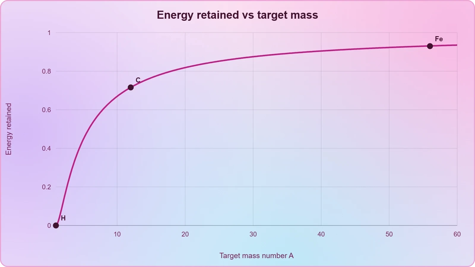
In an elastic collision, the fraction of energy retained by a neutron depends on the target mass ##[A]##. The average energy loss per collision scales with ##[1 - \dfrac{(A-1)^2}{2A}\ln\dfrac{A+1}{A-1}]##, which approaches unity for hydrogen and becomes negligible for heavy nuclei. Light elements are therefore indispensable moderators.
For a head-on collision with a proton, the neutron can transfer essentially all its energy, a consequence of the near-equal masses. This is why water and polyethylene outperform concrete and steel as moderators despite lower density. Designers exploit this mass-matching principle systematically.
Practical Moderator Materials
Water, heavy water, polyethylene, and borated plastics dominate practical moderator design. Heavy water offers lower parasitic absorption but costs far more, so ordinary water and hydrogenous polymers serve most applications. Concrete contributes moderation through its hydrogen content, though its effectiveness varies with moisture.
Moderator thickness must be tuned to the source spectrum: too thin and fast neutrons escape, too thick and capture gamma rays accumulate. Facilities therefore optimize thickness computationally, validating predictions with neutron survey instruments calibrated for the relevant energy range.
Absorption and Capture Reactions
Once neutrons reach thermal energies, capture reactions convert them into stable nuclei or secondary radiation that must be managed. The choice of absorber determines both the effectiveness of the shield and the nature of the residual hazard.
Boron and Lithium Capture
Boron-10 exhibits a thermal capture cross-section near ##[3840\ \text{barns}]##, producing an alpha particle and lithium-7 with a ##[2.79\ \text{MeV}]## energy release. This reaction emits no significant gamma radiation, making boron exceptionally attractive for shielding where secondary photons are a concern.
Lithium-6 offers a similar advantage, capturing neutrons to produce tritium and helium without gamma emission. Borated polyethylene combines moderation and capture in a single material, and it appears widely in shielding blankets, storage casks, and medical vault linings where compactness matters.
Hydrogen Capture and Gamma Production
Hydrogen capture emits a ##[2.223\ \text{MeV}]## gamma ray, so water and polyethylene shields generate secondary photon fields that require additional attenuation. Facilities often layer high-Z materials outside the moderator to absorb these capture gammas, creating a composite shield with distinct functional zones.
This layered architecture—moderator inside, absorber and gamma attenuator outside—represents the mature engineering solution. Each layer addresses a specific physical process, and the overall design balances thickness, weight, cost, and the need to keep dose rates below regulatory limits.
Composite Shielding Design in Practice
Real facilities rarely rely on a single material; instead they assemble layered shields that moderate, capture, and attenuate in sequence. The design process integrates physics calculations, engineering constraints, and regulatory requirements into a coherent whole.
Layered Shield Architecture
A typical neutron shield places hydrogenous moderator nearest the source, followed by a boron-loaded capture layer, then a dense gamma attenuator such as steel or lead. This sequence ensures fast neutrons slow before capture, and capture gammas are absorbed before escaping. Each interface requires careful material selection.
Concrete walls often serve dual roles, providing structural support and bulk moderation, while borated polyethylene panels add capture capability where space is limited. The resulting composite must be validated by measurement, since construction tolerances and material variability can shift performance.
Dose Limits and Regulatory Compliance
Facilities design to dose constraints derived from occupational and public exposure limits, typically expressed in millisieverts per year. Shielding calculations must demonstrate compliance under conservative assumptions, and periodic surveys confirm that as-built conditions match design intent. Documentation supports licensing and inspection.
Neutron dosimetry requires instruments sensitive to the relevant energy range, since conventional gamma survey meters respond poorly to neutrons. Facilities therefore maintain calibrated neutron rem-meters and personal dosimeters, and they train staff to interpret readings correctly in mixed fields.
We Also Published
Monitoring, Dosimetry, and Operational Safety
Shielding is only one pillar of neutron safety; continuous monitoring and disciplined operational practice complete the protective framework. Facilities combine area surveys, personal dosimetry, and administrative controls to verify that engineered barriers perform as intended.
Instrumentation and Calibration
Neutron survey instruments use detectors such as boron trifluoride proportional counters or helium-3 tubes, often surrounded by polyethylene moderators to approximate dose-equivalent response. Calibration against known sources ensures readings reflect actual risk rather than raw count rates, which vary strongly with energy.
Personal neutron dosimeters include track-etch films, thermoluminescent albedo badges, and electronic devices, each with distinct energy response and reporting characteristics. Facilities select instruments matched to their source spectra and maintain rigorous calibration schedules to preserve measurement credibility.
Administrative Controls and Training
Engineered shielding cannot substitute for trained personnel who understand neutron hazards and follow controlled-area procedures. Access restrictions, posted dose rates, and periodic drills reinforce safe behavior, while radiation protection officers review work plans before high-dose tasks proceed.
Facilities also manage activation hazards, since neutron irradiation can render structural materials and tools radioactive. Careful material selection, decay storage, and contamination surveys prevent unexpected exposures during maintenance and decommissioning activities.
Emerging Materials and Future Directions
Shielding technology continues to evolve as facilities demand lighter, thinner, and more effective barriers for compact accelerators, space systems, and advanced reactors. Research focuses on nanostructured materials, novel boron compounds, and computational optimization that tailors shields to specific spectra.
Advanced Hydrogenous and Boron-Rich Materials
Engineered composites incorporating boron carbide nanoparticles, metal hydrides, and polymer blends promise higher capture efficiency per unit mass. Metal hydrides such as lithium hydride offer exceptional hydrogen density, though handling and stability constraints limit widespread deployment in routine facilities.
Additive manufacturing enables geometrically optimized shields with graded compositions, placing moderator and absorber precisely where needed. These techniques reduce weight and volume, valuable in spacecraft and mobile systems where every kilogram carries a penalty and shielding mass competes with mission payload.
Computational Modeling and Validation
Monte Carlo transport codes such as MCNP and Geant4 allow designers to simulate neutron histories through complex geometries, predicting dose rates before construction begins. Validation against benchmark experiments remains essential, since modeling errors can propagate into unsafe designs if left unchecked.
Machine learning increasingly assists in optimizing shield configurations, exploring material combinations far faster than manual iteration. Nevertheless, physical validation and conservative margins remain indispensable, because regulatory acceptance depends on demonstrated performance rather than computational elegance alone.
Worked Calculations for Neutron Attenuation
Quantitative reasoning transforms shielding from intuition into engineering, and a handful of representative calculations illustrate the governing relationships. These examples demonstrate how facilities translate physical principles into concrete thickness and dose estimates.
Moderation and Energy Loss
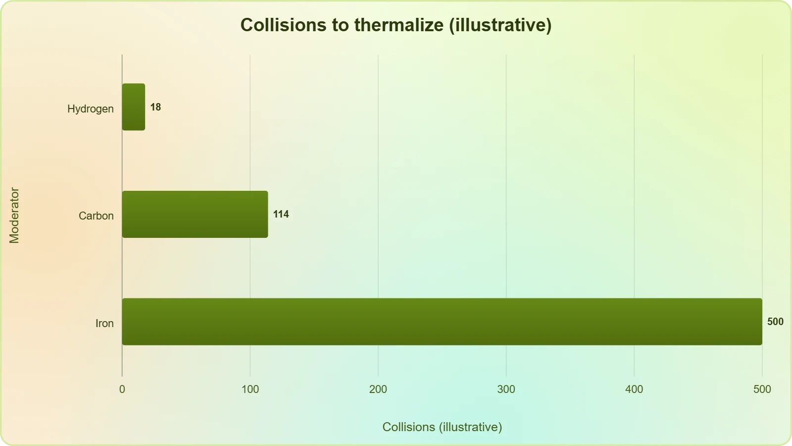
The average logarithmic energy decrement per collision, ##[\xi]##, quantifies moderation efficiency. For hydrogen, ##[\xi \approx 1]##, while for carbon ##[\xi \approx 0.158]## and for lead ##[\xi \approx 0.009]##. The number of collisions to thermalize from ##[E_0]## to ##[E_t]## follows directly.
For a ##[2\ \text{MeV}]## neutron slowing to ##[0.025\ \text{eV}]## in hydrogen, ##[n \approx \ln(8\times10^{7})/1 \approx 18]## collisions. In carbon the same moderation requires roughly ##[114]## collisions, illustrating why hydrogenous materials dominate practical shield design.
Attenuation and Mean Free Path
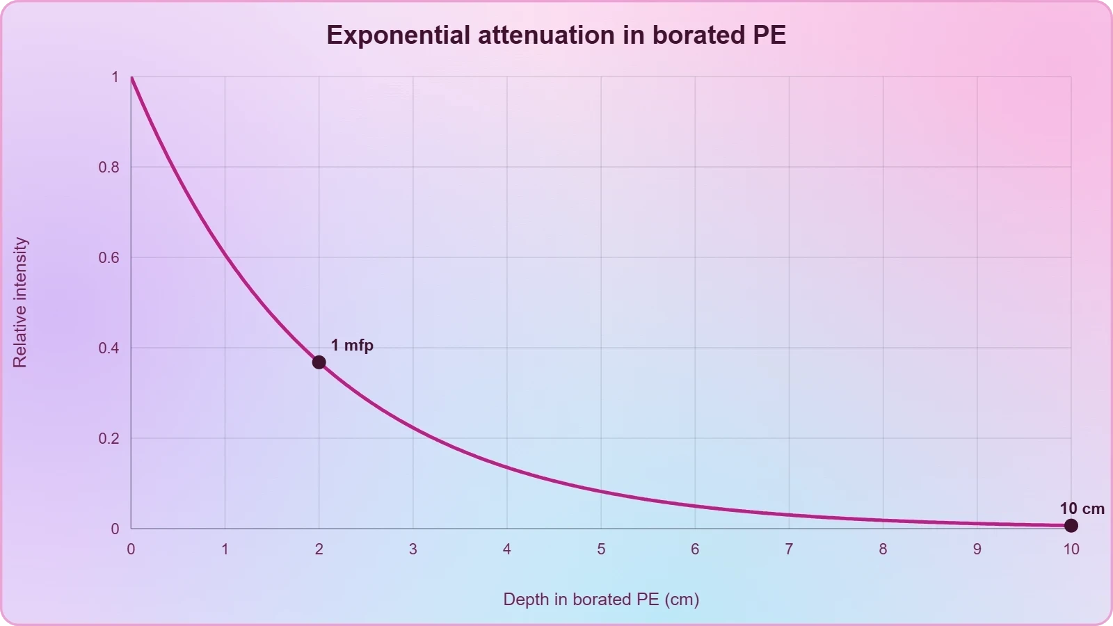
Attenuation follows an exponential law governed by the macroscopic cross-section ##[\Sigma]##, the product of number density and microscopic cross-section. The mean free path ##[\lambda = 1/\Sigma]## sets the characteristic distance over which intensity falls by ##[1/e]##.
For thermal neutrons in boron-loaded polyethylene with ##[\Sigma \approx 0.5\ \text{cm}^{-1}]##, the mean free path is about ##[2\ \text{cm}]##, so a ##[10\ \text{cm}]## layer attenuates intensity by ##[e^{-5} \approx 0.0067]##, a reduction of more than two orders of magnitude.
Dose Rate and Shielding Thickness
Dose rate scales with neutron flux and the fluence-to-dose conversion coefficient ##[h]##, which depends strongly on energy. Facilities compute unshielded dose rates, then apply attenuation factors to determine required thickness for compliance with limits.
If an unshielded flux of ##[10^{8}\ \text{cm}^{-2}\text{s}^{-1}]## yields an unacceptable dose rate, designers calculate the attenuation factor needed and solve for thickness. A required factor of ##[10^{4}]## with ##[\Sigma = 0.5\ \text{cm}^{-1}]## demands ##[x = \ln(10^{4})/0.5 \approx 18.4\ \text{cm}]## of borated polyethylene.
Capture Gamma Attenuation
Secondary capture gammas require their own attenuation calculation using photon cross-sections. A ##[2.223\ \text{MeV}]## gamma in lead has a linear attenuation coefficient near ##[0.55\ \text{cm}^{-1}]##, so a ##[5\ \text{cm}]## lead layer reduces intensity by ##[e^{-2.75} \approx 0.064]##.
Combining neutron and gamma calculations ensures the composite shield addresses both primary and secondary hazards. Facilities iterate between layers until total dose satisfies constraints, then verify by measurement after construction.
Activation and Decay Estimates
Neutron activation follows the saturation formula, where activity approaches a steady state determined by production rate and decay constant. Facilities use this relationship to estimate residual activity in components exposed to prolonged irradiation.
For a component with production rate ##[R]## and half-life ##[T_{1/2}]##, activity after several half-lives approaches ##[R]##. This informs decisions about decay storage duration and the timing of maintenance work in activated areas.
Skyshine and Boundary Dose
Skyshine calculations estimate dose at site boundaries from neutrons scattered by the atmosphere. Simplified models relate boundary dose to source strength, distance, and an empirical scattering coefficient, providing conservative estimates for licensing submissions.
Where ##[S]## is source strength, ##[k]## an empirical coefficient, and ##[d]## the distance to the boundary, this approximation guides initial design before detailed Monte Carlo analysis. Facilities then refine estimates with full transport simulations.
Shield Thickness Optimization
Optimization balances attenuation against weight and cost, often expressed as minimizing a composite objective function. Designers vary layer thicknesses subject to dose constraints, seeking the lightest configuration that satisfies all requirements.
This constrained minimization yields practical layer dimensions, and sensitivity analysis reveals which parameters most influence performance. Robust designs maintain margin against material variability and construction tolerances.
Neutron Flux from a Point Source
Flux from an isotropic point source falls with the inverse square of distance, providing a baseline before shielding is applied. This geometric attenuation often proves as important as material selection in facility layout.
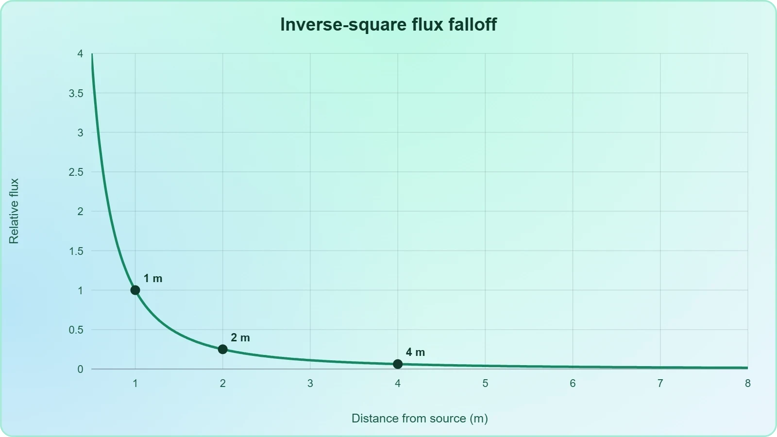
Doubling the distance from a source reduces flux by a factor of four, a principle that informs room layout and the placement of control areas. Shielding then supplements geometric separation where distance alone is insufficient.
Thermal Capture Rate in Boron
The capture rate per unit volume depends on thermal flux, boron number density, and the microscopic cross-section. This calculation determines how much boron loading a polymer requires for effective capture.
With ##[\phi_{\text{th}} = 10^{6}\ \text{cm}^{-2}\text{s}^{-1}]##, ##[N_B = 10^{22}\ \text{cm}^{-3}]##, and ##[\sigma_B = 3840\ \text{b} = 3.84\times10^{-21}\ \text{cm}^{2}]##, the capture rate reaches roughly ##[3.84\times10^{7}\ \text{cm}^{-3}\text{s}^{-1}]##, confirming strong absorption.
Dose Equivalent from Fluence
Converting fluence to dose equivalent requires energy-dependent quality factors, since neutrons of different energies produce different biological damage. Facilities apply fluence-to-dose conversion coefficients tabulated by international bodies.
For a fluence of ##[10^{9}\ \text{cm}^{-2}]## at ##[1\ \text{MeV}]## with ##[h \approx 400\ \text{pSv}\cdot\text{cm}^{2}]##, the dose equivalent reaches approximately ##[0.4\ \text{mSv}]##, a value that informs access restrictions and monitoring thresholds.
From our network :
- EV 2.0: The Solid-State Battery Breakthrough and Global Factory ExpansionDiscover the impact of the Solid-State Battery Breakthrough on the EV market. Learn about CATL and BYD stock growth, global factory expansion in Europe, and the future of EV 2.0 technology.
- 10 Physics Numerical Problems with Solutions for IIT JEEPrepare for IIT JEE with 10 physics numerical problems, complete with detailed solutions and conceptual explanations. Ideal for mastering kinematics, thermodynamics, electromagnetism, and optics.
- Mastering DB2 LUW v12 Tables: A Comprehensive Technical GuideComprehensive guide on DB2 LUW v12 tables. Explore CREATE TABLE syntax, BLU Acceleration, range partitioning, data types, and security features for IBM DB2 LUW v12.
- Mastering DB2 12.1 Instance Design: A Technical Deep Dive into Modern Database ArchitectureComprehensive guide to DB2 12.1 Instance Design. Explore architectural components, HADR setup, buffer pool tuning, and security policies for IBM DB2 12.1. Includes 10 functional SQL and Shell samples.
- 98% of Global MBA Programs Now Prefer GRE Over GMAT Focus EditionExplore why 98% of global MBA programs now prefer the GRE over GMAT Focus. Learn about the shorter GRE format, verbal logic importance, and strategic versatility for students.
- Analyzing Trump Deportation Numbers Insights Into The 2026 Immigration Crackdown
- AI-Powered 'Precision Diagnostic' Replaces Standard GRE Score ReportsDiscover the new GRE Precision Diagnostic. Learn how AI-powered behavioral analytics and time-to-solve tracking are replacing standard GRE score reports to empower students.
- Vite 6/7 'Cold Start' Regression in Massive Module GraphsIn-depth analysis of Vite 6/7 cold start regressions in massive module graphs. Learn about barrel file issues, pre-bundling optimizations, and how to improve Vite dev server performance.
- Trump Political Strategy How Geopolitical Stunts Serve As Media Diversions
RESOURCES
- Neutron radiation - Wikipediaen.wikipedia.orgNeutron radiation protection relies on radiation shielding. Due to the high kinetic energy of neutrons, this radiation is considered the most severe and ...
- Why is neutron radiation best shielded with materials made ... - Redditreddit.comJan 10, 2014 ... So an effective neutron shield will be able to 1) slow neutrons down and 2) capture them. Hydrogen also has…
- Robust 2D layered MXene matrix–boron carbide hybrid films for ...nature.comOct 31, 2023 ... ... neutron radiation shielding. However, the surface density of boron, which is directly related to the neutron-shielding capabilities of boron ...
- 32 - Shielding Radiation. - Nuclear Regulatory Commissionnrc.govRadiation Energy. The greater the energy of the radiation (e.g., beta particles, gamma rays, neutrons) the thicker the shield must be.
- Development and application analysis of high-energy neutron ...sciencedirect.comOriginal Article. Development and application analysis of high-energy neutron radiation shielding materials from tungsten boron polyethylene.
- What is Neutron Shielding and What are the Most Effective Materials ...raybloc.comSep 17, 2024 ... Hydrogen plays a crucial role in neutron shielding due to its ability to attenuate fast neutrons. The light atomic mass…
- Neutron Shielding Materialseichrom.comLike gamma radiation, neutrons undergo scattering and absorption interactions with matter. These interactions form the basis for methods used to shield and ...
- Polyvinyl Alcohol and Medium Density Polyethylene Composite ...ntrs.nasa.govPolyvinyl Alcohol and Medium Density Polyethylene Composite Materials for Neutron Radiation Shielding Manned spacecraft venturing beyond the Earth's Van ...
- Neutron shielding materials - Radiation Shielding - Röchling Grouproechling.comRöchling offers high-performance materials specifically developed for neutron shielding made of thermoplastics, laminated densified wood and glass fibre ...
- A comparative analysis of gamma and neutron radiation shielding ...pubmed.ncbi.nlm.nih.govMar 11, 2026 ... A comparative analysis of gamma and neutron radiation shielding properties of Gd2O3 nanoparticles within HDPE composites irradiated with ...
- An Innovative Material for Neutron Radiation Shielding - arXivarxiv.orgJun 5, 2024 ... The study findings showed that a 30 cm thick shield effectively blocked 95% of the total neutrons and 92% of…
- Neutron Radiation Shielding Strategies for Glovebox Applicationsosti.govGlovebox operation and geometry limit the shielding thickness to a few inches. A basic understanding of the nature of neutron emission, neutron moderation, and.
- Borated & Pure Polyethylene Neutron Shielding - MarShieldmarshield.comPlasti-Shield is a borated polyethylene neutron shielding material designed to slow and absorb neutron radiation. It is used across medical, nuclear ...
- Boron Nitride Nanotube Reinforced Polyethylene Composite for ...ttu-ir.tdl.orgJul 13, 2025 ... Boron nitride nanotubes (BNNTs) and other boron-enriched materials offer superior thermal neutron radiation shielding due to their high cross- ...
- Project - NASA TechPorttechport.nasa.govDec 18, 2025 ... Contemporary radiation shields developed for aerospace cannot readily stop such neutrons. Using terrestrial neutron radiation shielding would ...