The world of iit jee circuits can be daunting, but fear not! We’re embarking on an exploration of current electricity, a crucial topic for any aspiring engineer. This journey will equip you with the tools to confidently approach circuit analysis. We’ll break down complex concepts into manageable steps, making sure you grasp the fundamental principles. Get ready to unravel the mysteries of electrical circuits!
Table of Contents
Read More
Welcome, future engineers! Today, we’ll dive into the fascinating world of electrical circuits, specifically focusing on numerical problems relevant to the IIT JEE exam. Mastering these concepts is crucial for success, and we’ll break down the essential principles step-by-step. Our focus is to help you strengthen your circuit analysis skills, and to prepare you for the challenges ahead. Let’s get started!
Understanding Circuit Fundamentals
To truly grasp the essence of iit jee circuits, we must first revisit the basics. What governs the flow of current? How do resistors behave in series and parallel? The answers to these questions form the bedrock of our understanding, and without a strong foundation, we risk getting lost in the complexities. This section is designed to provide you with clarity and confidence.
Ohm’s Law and Its Implications
Ohm’s Law, represented as ##V = IR##, is the cornerstone of circuit analysis. It defines the relationship between voltage (V), current (I), and resistance (R). The current through a conductor between two points is directly proportional to the voltage across the two points, and inversely proportional to the resistance between them. Understanding this simple yet powerful law allows us to calculate various circuit parameters.
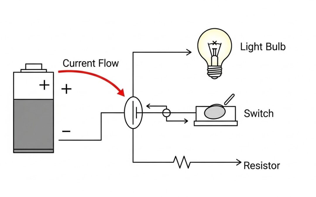
Consider a simple circuit with a 12V battery and a 2Ω resistor. Using Ohm’s Law, we can find the current: ##I = V/R = 12V / 2Ω = 6A##. This illustrates how the current is directly proportional to the voltage. If we increase the voltage, the current will increase proportionally, and if we increase the resistance, the current will decrease. This fundamental understanding is crucial for solving complex iit jee circuits problems.
Series and Parallel Resistor Combinations
Resistors can be connected in series or parallel, and the way they are connected greatly affects the total resistance of the circuit. In a series combination, resistors are connected end-to-end, and the total resistance is the sum of individual resistances. This means that the current flowing through each resistor is the same.
For a parallel combination, resistors are connected across the same two points, and the reciprocal of the total resistance is the sum of the reciprocals of the individual resistances. This means that the voltage across each resistor is the same. Understanding these combinations is crucial for simplifying complex iit jee circuits. Consider two resistors, 2Ω and 4Ω, in series. The total resistance is 6Ω. If these were in parallel, the total resistance would be approximately 1.33Ω. These simple calculations form the basis for more complicated circuit analysis.
Solving Complex Circuit Problems
Now, let’s apply our knowledge to solve some complex circuit problems. This section will guide you through a series of problems, providing detailed explanations and step-by-step solutions. We will focus on various aspects, including current distribution, voltage drops, and equivalent resistance calculations. Each problem will illustrate the practical application of the concepts we’ve discussed.
Problem 1: Equivalent Resistance
Calculate the equivalent resistance between points A and B in the following circuit. The circuit consists of multiple resistors arranged in a combination of series and parallel connections. You’ll need to simplify the circuit step-by-step, combining resistors until you arrive at a single equivalent resistance value. This process is fundamental to circuit analysis, making it possible to understand and predict the overall behavior of a complex network.
Let’s consider a circuit with three resistors: R1 = 2Ω, R2 = 4Ω, and R3 = 6Ω. R1 and R2 are in series, and the combination is in parallel with R3. First, combine R1 and R2: ##R_{12} = R1 + R2 = 2Ω + 4Ω = 6Ω##. Then, find the equivalent resistance of R12 and R3 in parallel: ### \frac{1}{R_{eq}} = \frac{1}{R_{12}} + \frac{1}{R3} = \frac{1}{6} + \frac{1}{6} = \frac{1}{3}###, therefore, ###R_{eq} = 3Ω###. This is how you simplify iit jee circuits problem.
Problem 2: Current Distribution
Determine the current flowing through each resistor in the following circuit. Given a circuit with multiple resistors and a voltage source, we need to apply Ohm’s Law and the principles of series and parallel circuits to find the current through each component. This requires careful analysis of the circuit’s structure and the application of relevant formulas. This ability to predict current flow is crucial for designing and troubleshooting electrical systems.
Consider a circuit with a 12V battery, a 2Ω resistor (R1), and a 4Ω resistor (R2) in series. The total resistance is:
###R_{\text{total}} = R_1 + R_2 = 2\Omega + 4\Omega = 6\Omega###
The total current is:
###I = \dfrac{V}{R} = \dfrac{12V}{6\Omega} = 2A###
Since the resistors are in series, the current through both R1 and R2 is the same, i.e., 2A.
The voltage drop across R1 is:
###V_1 = I \cdot R_1 = 2A \cdot 2\Omega = 4V###
The voltage drop across R2 is:
###V_2 = I \cdot R_2 = 2A \cdot 4\Omega = 8V###
Thus, the voltage is divided proportionally across the resistors, and the sum of the drops equals the source voltage (4V + 8V = 12V). This demonstrates how to determine current and voltage distribution in a simple series circuit. The same reasoning can be extended to analyze more complex networks.
Further Exploration
Let’s move on to more challenging scenarios, expanding your ability to tackle a variety of circuit analysis questions. These problems aim to refine your problem-solving skills and enhance your understanding of circuit principles. This includes an introduction to more complex circuit elements and their behavior.
Problem 3: Voltage Drop Calculation
Calculate the voltage drop across each resistor in a given circuit. This involves understanding the relationship between current, resistance, and voltage. You will need to apply Ohm’s Law and the principles of series and parallel circuits to determine the voltage across each resistor. This is a crucial skill for circuit design and analysis, allowing you to predict the behavior of circuit components under various conditions.
Consider a circuit with a 12V source and two resistors (R1 = 3Ω and R2 = 6Ω) connected in series. First, find the total resistance:
###R_{\text{total}} = R_1 + R_2 = 3\Omega + 6\Omega = 9\Omega###
Now calculate the total current:
###I = \dfrac{V}{R} = \dfrac{12V}{9\Omega} \approx 1.33A###
Since the resistors are in series, the same current flows through both R1 and R2.
The voltage drop across R1 is:
###V_1 = I \cdot R_1 = 1.33A \cdot 3\Omega \approx 4V###
The voltage drop across R2 is:
###V_2 = I \cdot R_2 = 1.33A \cdot 6\Omega \approx 8V###
The sum of the voltage drops equals the source voltage: ###V_1 + V_2 \approx 4V + 8V = 12V###, confirming Kirchhoff’s Voltage Law. This step-by-step calculation is a fundamental method in solving IIT JEE circuit problems.
Problem 4: Power Dissipation
To determine the power dissipated by each resistor, we apply the general power formulas:
###P = VI = I^2R = \dfrac{V^2}{R}###
Example: Consider a 6V source and a 2Ω resistor.
The current is:
###I = \dfrac{V}{R} = \dfrac{6V}{2\Omega} = 3A###
Now calculate the power dissipated:
- Using ##P = VI##: ###P = 6V \cdot 3A = 18W###
- Using ##P = I^2R##: ###P = (3A)^2 \cdot 2\Omega = 18W###
- Using ##P = V^2/R##: ###P = (6V)^2 / 2\Omega = 36/2 = 18W###
All three methods give the same result, confirming consistency. Understanding power dissipation is crucial for selecting appropriate resistor ratings and ensuring the circuit operates safely within limits—an essential step in IIT JEE circuit analysis.
Key Takeaways
Congratulations! You’ve successfully navigated a series of circuit problems designed to strengthen your understanding of electrical circuits. By mastering the fundamentals of Ohm’s Law, series and parallel circuits, and power calculations, you’ve built a solid foundation for tackling more complex problems. Remember to practice consistently, and always strive to understand the underlying principles.
Similar Problems
Here are some similar problems to test your understanding and reinforce your skills:
- Problem: A 10Ω and a 20Ω resistor are in series with a 6V battery. Find the current. Answer: 0.2A
- Problem: Two 5Ω resistors are in parallel. What is the equivalent resistance? Answer: 2.5Ω
- Problem: Calculate the voltage drop across a 3Ω resistor if 2A current flows through it. Answer: 6V
- Problem: Find the power dissipated by a 4Ω resistor if 3A current flows through it. Answer: 36W
- Problem: Determine the equivalent resistance of three 6Ω resistors in parallel. Answer: 2Ω
| Concept | Description | Formula/Example |
|---|---|---|
| Ohm’s Law | Defines the relationship between voltage, current, and resistance. | ##V = IR## |
| Series Resistors | Resistors connected end-to-end. Total resistance is the sum of individual resistances. | ##R_{total} = R1 + R2 + …## |
| Parallel Resistors | Resistors connected across the same points. Reciprocal of total resistance is the sum of reciprocals. | ### rac{1}{R_{eq}} = rac{1}{R1} + rac{1}{R2} + …### |
| Power Dissipation | The rate at which energy is consumed by a resistor. | ##P = VI = I^2R = V^2/R## |
| Current Distribution | How current divides in a parallel circuit. | Current divides inversely proportional to resistance. |
We also Published
RESOURCES
- Complicated Circuits – Study Material for IIT JEE | askIITians
- NEED URGENT HELP REGARDING IIT JEE PREPARATION : r …
- Solved Examples Of Complicated Circuits – Study Material for IIT JEE
- Buy THE AHA GUIDE TO Electric Circuits for CBSE + IIT JEE + …
- Physics Quiz on Series and Parallel Circuits for IIT JEE, NEET …
- Electricity & Magnetism | IIT JEE | Unacademy
- Capacitors – YouTube
- Electric Current and Circuits | IIT JEE | Unacademy
- Should I learn complex impedance for the JEE Advanced? – Quora
- Circuit Solving – Important Concepts and Tips for JEE


0 Comments